Combustion device
a combustion device and combustion technology, applied in combustion types, combustion using lump and pulverulent fuel, lighting and heating apparatus, etc., can solve the problems of increasing the occurrence of tube leakage, complex arrangement of ducts, and increasing the difficulty of reducing so as to reduce the nox concentration in the exhaust gas, reduce the nox concentration, and control the thermal absorption of the furnace
- Summary
- Abstract
- Description
- Claims
- Application Information
AI Technical Summary
Benefits of technology
Problems solved by technology
Method used
Image
Examples
embodiment 1
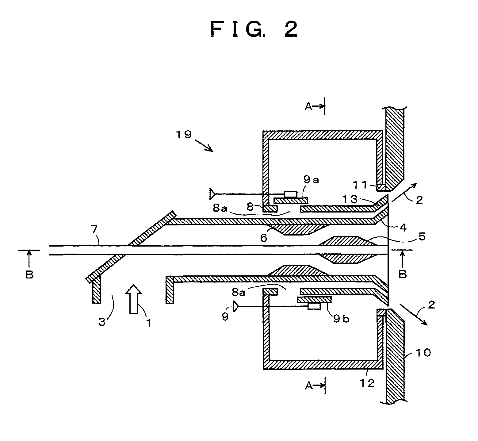
[0054]FIG. 3(a) shows a perspective view of the wind box 12 of the pulverized coal burner 19 according to this embodiment, and FIG. 4 shows a cross-sectional view (FIG. 4(a)) taken along a line A-A in FIG. 2 and a cross-sectional view (FIG. 4(b)) taken along a line B-B in FIG. 2. It is to be noted that each dark arrow shown in FIG. 4 and subsequent drawings represents an inflow direction of the combustion air.
[0055]Further, a heavy oil nozzle 7 and the pulverized coal nozzle 3 are not shown in FIG. 4, and the heavy oil nozzle 7 and the pulverized coal nozzle 3 are arranged in a cylindrical through hole of the wind box 12. A furnace wall of the through hole constitutes an outer wall of the secondary air nozzle 8.
[0056]As shown in FIG. 4, the wind box 12 having combustion air inlet openings 12a and 12b provided in a direction vertical to a central axis direction of the pulverized coal burner 19, and the secondary air nozzle 8 is arranged as if it is inserted in the through hole provid...
embodiment 2
[0067]In this embodiment, as shown in FIG. 8 and FIG. 9, a wind box 12 into which combustion air flows only from the upper side that is vertical to a central axis direction of a burner 19 is provided, and a plurality of partition plate 14 and revolving dampers 15 are provided in the wind box 12 so that the momentum of the combustion air injected into a furnace can be deviated depending on each of upper and lower sides by adjusting the dampers 15.
[0068]As shown in FIG. 8, in this embodiment, the partition plates 14 are provided so as to divide into three parts the wind box 12 into which the combustion air flows from one direction, i.e., either upper combustion air inlet opening 12a or 12b vertical to the central axis direction of the burner 19. Furthermore, the dampers 15a, 15b, and 15b as air capacity adjusters are provided on the upstream side of trifurcated air inflow paths in the wind box 12, respectively. Therefore, air flows into the upper side of the burner 19 from a central p...
embodiment 3
[0075]This embodiment shown in FIG. 12 and FIG. 13 has a configuration that a wind box 12 into which combustion air flows only from lower combustion air inlet openings 12a and 12b vertical to a central axis of the burner 19 is provided, the inside of the wind box 12 is partitioned by a plurality of partition plates 14, dampers 15b, 15a, and 15b or 15b, 15aa, 15ab, and 15b are provided in respective combustion air nozzles in the wind box 12 partitioned by the partition plates 14, and the momentum of the combustion air injected into a furnace 18 from the burner 19 is deviated depending on each of upper and lower sides of the burner 19 by adjusting opening / closing degrees of the dampers 15b, 15a, and 15b or 15b, 15aa, 15ab, and 15b.
[0076]In this embodiment shown in FIG. 12, the partition plates 14 and 14 are provided so as to divide the wind box 12, into which the combustion air flows from only one lower direction which is a direction vertical to the central axis direction of the burn...
PUM
 Abstract
Description
Claims
Application Information
 - R&D
- Intellectual Property
- Life Sciences
- Materials
- Tech Scout
- Unparalleled Data Quality
- Higher Quality Content
- 60% Fewer Hallucinations
Browse by: Latest US Patents, China's latest patents, Technical Efficacy Thesaurus, Application Domain, Technology Topic, Popular Technical Reports.
© 2025 PatSnap. All rights reserved.Legal|Privacy policy|Modern Slavery Act Transparency Statement|Sitemap|About US| Contact US: help@patsnap.com


