
Injection molded body and method for producing same

a technology of injection molding and body, which is applied in the direction of transportation and packaging, synthetic resin layered products, chemistry apparatus and processes, etc., can solve the problems of large defect of anisotropy warping, inability to obtain satisfactory advantages, and inability to generate strength and shrinkage, so as to achieve low warping property and suppress the effect of anisotropy

Active Publication Date: 2013-12-19
TORAY IND INC
View PDF2 Cites 12 Cited by
  • Summary
  • Abstract
  • Description
  • Claims
  • Application Information

AI Technical Summary

Benefits of technology

The injection molded body and method described in this patent allow for a smaller thickness core layer, which results in less warping and reduced anisotropy between the core layer and the skin layer. This makes the molded body more suitable for applications that require low warping, such as housing, chassis, and gears of electronic equipment. The method can also produce larger parts with larger areas.

Problems solved by technology

However, if injection molding is carried out using the fiber reinforced thermoplastic resin pellets thus obtained, because the fibrous filler is oriented in a core layer in a direction perpendicular to a resin flow direction at the time of injection molding and oriented in a skin layer in the resin flow direction, anisotropy is generated in strength and shrinkage.
As a result, with respect to a molded body obtained, there has been a defect that its warping becomes great.
However, even if the long fiber pellets are used, when a usual injection molding is carried out, because the orientation directions of fibrous filler are different between in the skin layer and in the core layer, it is still in a situation where a satisfactory advantage cannot be obtained.
Further, with respect to a method for reducing warping in a molded body, Patent document 3 describes an effect for reducing warping by giving a characteristic to a resin to be combined, but it does not intend to control warping from anisotropy of fiber orientation.
In this mold, orientation of fibers is disturbed by rotating the cavity surface to give a shear to a material to be molded into a molded body, but the quantity for disturbing the orientation is small, and there is a limitation in shape of the molded body.

Method used


Image

  • Injection molded body and method for producing same
  • Injection molded body and method for producing same
  • Injection molded body and method for producing same

Examples


example 1

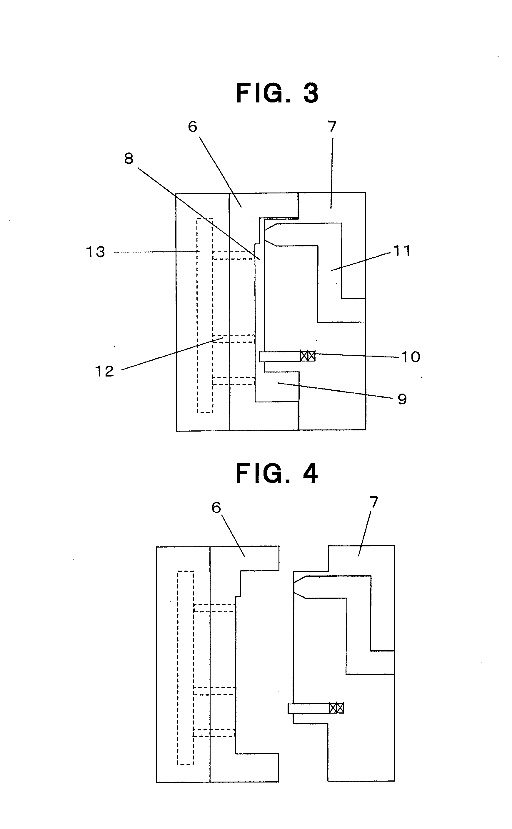
[0097]First, PAN based continuous carbon fiber bundles as the fibrous filler (b) were heated, and a molten resin was measured and applied thereto by a gear pump. Then, the resin was impregnated into the carbon fiber bundles in an atmosphere heated at a temperature higher than the temperature for melting, and a composite of the continuous carbon fiber bundles and the resin was obtained (impregnation step).

[0098]Next, the thermoplastic resin (a) was deposited into a hopper of an extruder, and by extruding it to a coating die at a melt-kneaded condition and at the same time supplying the above-described composite continuously into the coating die, the resin composition comprising the thermoplastic resin (a) was coated to the composite, and by controlling the discharge amount of the extruder and the supply amount of the composite, continuous fiber reinforced resin strands with a carbon fiber content of 20 wt. % were obtained (coating step).

[0099]Thereafter, the above-described continuou...

example 6

[0102]The same condition as that in Example 2 was employed other than changing the content of carbon fibers of the continuous fiber reinforced resin strands to 30 wt. %. The result of estimation of this molded body was excellent in mechanical properties and amount of warping as shown in Table 1.

example 16

[0115]First, PAN based continuous carbon fiber bundles as the fibrous filler (b) were heated, and a molten resin was measured and applied thereto by a gear pump. Then, the resin was impregnated into the carbon fiber bundles in an atmosphere heated at a temperature higher than the temperature for melting, and a composite of the continuous carbon fiber bundles and the resin was obtained (impregnation step).

[0116]Next, the thermoplastic resin (a) was deposited into a hopper of an extruder, and by extruding it to a coating die at a melt-kneaded condition and at the same time supplying the above-described composite continuously into the coating die, the resin composition comprising the thermoplastic resin (a) was coated to the composite, and by controlling the discharge amount of the extruder and the supply amount of the composite, continuous fiber reinforced resin strands with a carbon fiber content of 20 wt. % relatively to the sum with the thermoplastic resin (a) were obtained (coatin...


PUM

PropertyMeasurementUnit
lengthaaaaaaaaaa
lengthaaaaaaaaaa
thicknessaaaaaaaaaa

Abstract

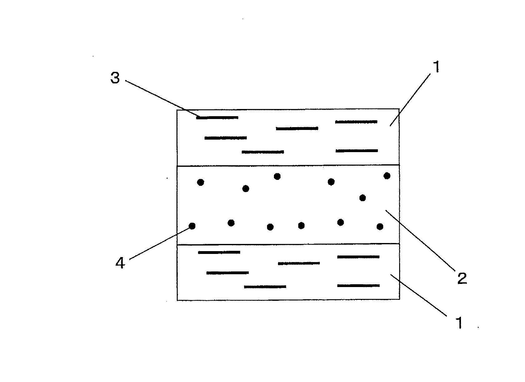
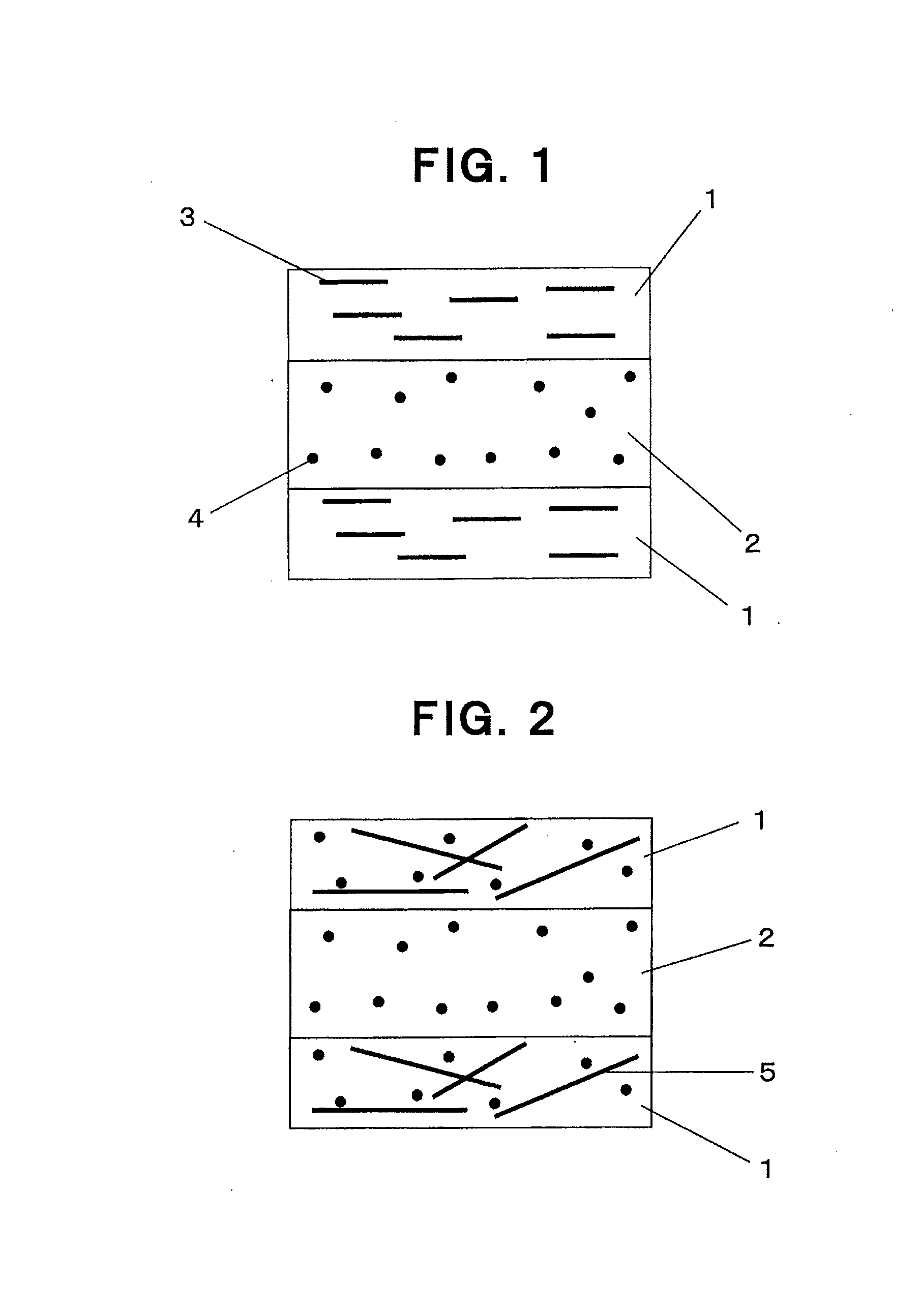
An injection molded body includes a fiber reinforced thermoplastic resin composition formed by combining fibrous filler with thermoplastic resin so that the weight average fiber length in the injection molded body is 300 μm or more, and the injection molded body has a skin layer, a core layer and a skin layer in this order in the thickness direction. The thickness of the core layer, in which the primary orientation direction of the fibrous filler is 40° or less when the direction perpendicular to the flow direction of the resin composition at the time of injection molding is set at 0°, is 20% or less relatively to the thickness of the injection molded body.

Description

TECHNICAL FIELD OF THE INVENTION[0001]The present invention relates to an injection molded body comprising a fiber reinforced thermoplastic resin composition formed by combining a thermoplastic resin and fibrous filler and a method for producing the same, and relates to an injection molded body wherein the weight average fiber length of the fibrous filler in the injection molded body is 300 μm or more, and which is little in variation of strength and low in warping, and a method for producing the same.[0002]In more detail, the present invention relates to an injection molded body formed with three layers of a skin layer, a core layer and a skin layer in the thickness direction by injection molding, which comprises a skin layer randomly oriented with fibrous filler and a core layer oriented with fibrous filler in a direction perpendicular to a flow direction at the time of injection molding and which is strengthened as the whole of the injection molded body and lowered in warping by ...

Claims


Application Information

Patent Timeline
Patent Type & Authority Applications(United States)
IPC IPC(8): B32B5/14B29C45/00
CPCB32B5/145B29C45/0005B29C45/561B29K2105/14Y10T428/249942B29C45/00B29C45/56
Inventor YAMAGUCHI, KOJITATEYAMA, MASARUSHIMIZU, NOBUHIKOIMAI, HIRONORI
Owner TORAY IND INC
Learn More