
Power transmission system and power transmitting apparatus

a transmission system and power technology, applied in the direction of transmission, circuit arrangement, inductance, etc., can solve the problems of increasing the scale of the circuit, the difficulty of reducing the size of the windings, and the complexity of the circuit of the whole power receiving apparatus, so as to reduce the turn ratio of the step-up transformer, reduce the parasitic capacitance, and reduce the size of the transformer

Inactive Publication Date: 2013-12-19
MURATA MFG CO LTD
View PDF3 Cites 12 Cited by
  • Summary
  • Abstract
  • Description
  • Claims
  • Application Information

AI Technical Summary

Benefits of technology

The present invention provides an electric-field coupling power transmission system and power transmitting apparatus that can stabilize an output voltage without adding complexity or size to the power receiving apparatus. This is achieved by decreasing the turns ratio of a step-up transformer and reducing parasitic capacitance generated in the secondary winding. These improvements result in a more compact and efficient transformer that can operate at higher frequencies, ultimately reducing the size of the overall system while maintaining high-frequency performance.

Problems solved by technology

However, in wireless power transmission using an electromagnetic field method, since the magnitude of magnetic flux passing through the windings has a strong influence on the electromotive force, high accuracy is required in the positional relationship between the primary and secondary windings and a reduction in the size of the windings is difficult.
However, the circuit of the whole power receiving apparatus becomes complex.
When a communication circuit is provided in the power receiving apparatus; the scale of the circuit increases and the cost also increases.
In addition, since interference with a power transmitting unit is likely to occur, communication control becomes complicated.
However, this is not a configuration for keeping an output voltage applied to the load circuit of a power receiving apparatus constant.

Method used


Image

  • Power transmission system and power transmitting apparatus
  • Power transmission system and power transmitting apparatus
  • Power transmission system and power transmitting apparatus

Examples


first embodiment

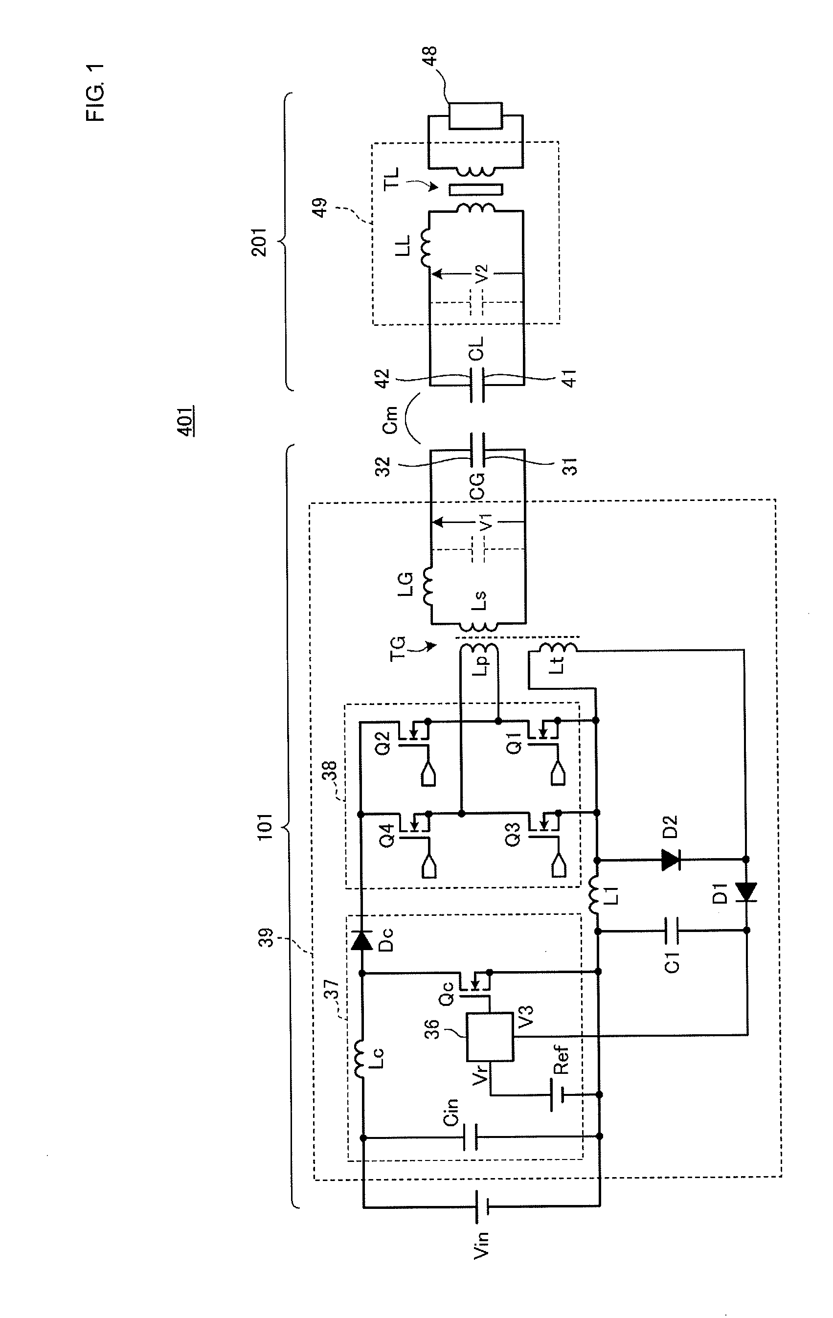
[0041]FIG. 1 is an equivalent circuit diagram of a power transmission system 401. In FIG. 1, a power transmitting apparatus 101 includes a power transmitting circuit 39, a passive electrode 31, and an active electrode 32. The passive electrode 31 and the active electrode 32 are power-transmitting-apparatus-side coupling electrodes. The power transmitting circuit 39 is formed of a step-up transformer TG, an inductor LG, a DC-AC conversion circuit 38, and a voltage conversion circuit 37. The DC-AC conversion circuit 38 generates, for example, a high-frequency voltage of a hundred kHz to several tens of MHz. A voltage step-up circuit formed of the step-up transformer TG and the inductor LG steps up a voltage generated by the DC-AC conversion circuit 38 and applies the stepped-up voltage between the passive electrode 31 and the active electrode 32. A capacitor CG represents a capacitance generated by the passive electrode 31 and the active electrode 32. The voltage step-up circuit and t...

second embodiment

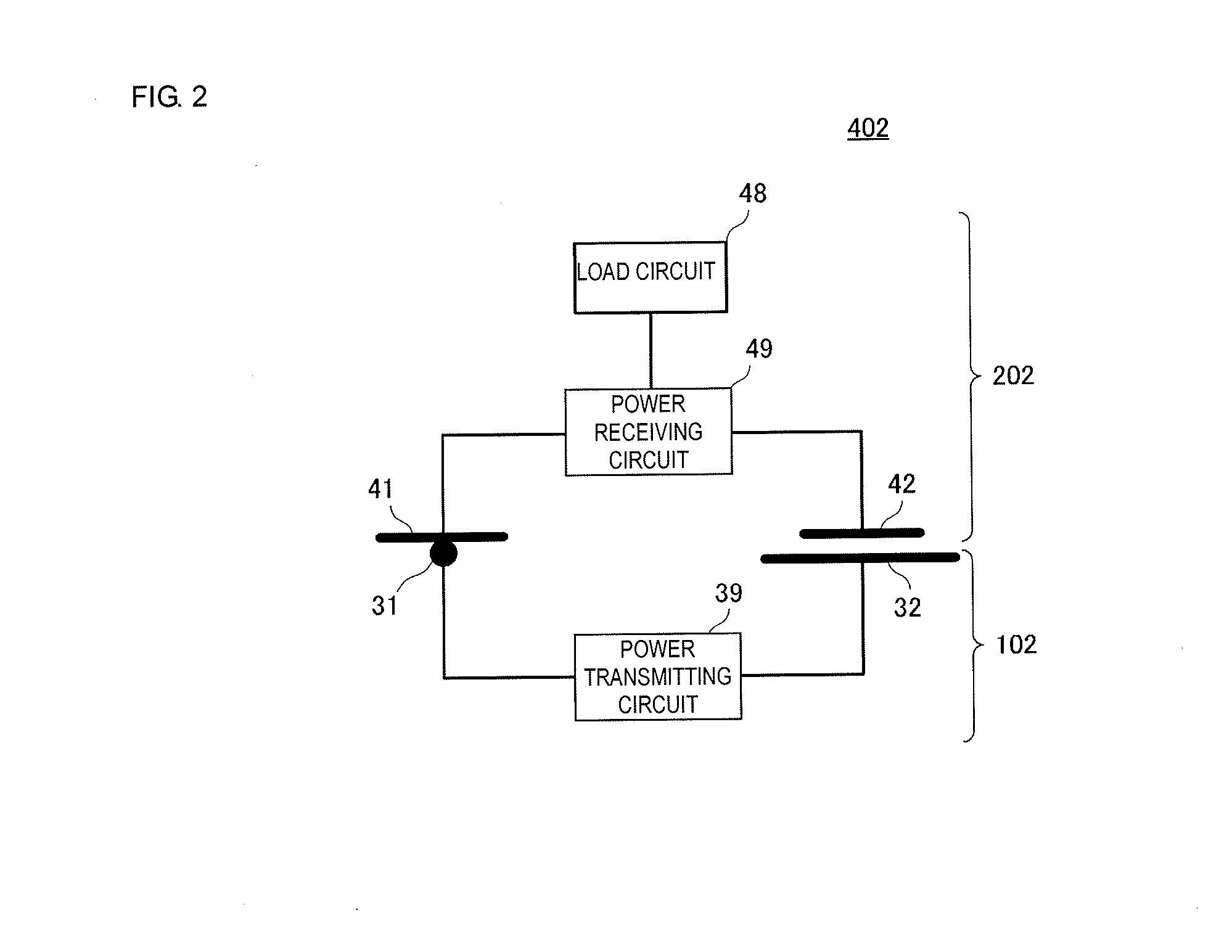
[0056]FIG. 2 is a simplified circuit diagram of a power transmission system 402 according to a second embodiment. The power transmission system 402 includes a power transmitting apparatus 102 and a power receiving apparatus 202. The power transmitting apparatus 102 includes a power-transmitting-apparatus-side passive electrode 31 and a power-transmitting-apparatus-side active electrode 32, and the power receiving apparatus 202 includes a power-receiving-apparatus-side passive electrode 41 and a power-receiving-apparatus-side active electrode 42.

[0057]A power transmitting circuit 39 is connected between the power-transmitting-apparatus-side active electrode 32 and the power-transmitting-apparatus-side passive electrode 31. A power receiving circuit 49 is connected between the power-receiving-apparatus-side active electrode 42 and the power-receiving-apparatus-side passive electrode 41, and a load circuit 48 is connected to the power receiving circuit 49.

[0058]The power transmitting c...

third embodiment

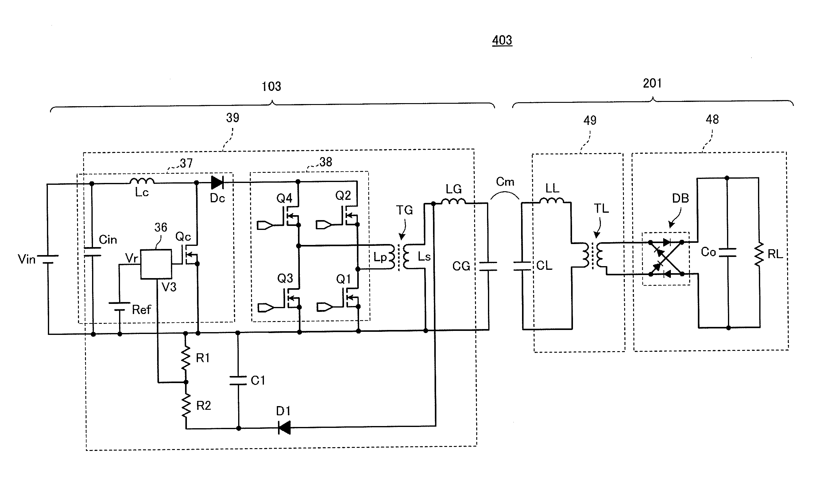
[0064]FIG. 4 is a circuit diagram of a power transmission system 403 according to a third embodiment. The power transmission system 403 includes a power transmitting apparatus 103 and a power receiving apparatus 201. A capacitor CG represents a capacitance generated by a passive electrode and an active electrode forming power-transmitting-apparatus-side coupling electrodes. A capacitor CL represents a capacitance generated by a passive electrode and an active electrode forming power-receiving-apparatus-side coupling electrodes.

[0065]The configuration of the power receiving apparatus 201 is the same as that of the power receiving apparatus described in the first embodiment. Here, a load circuit 48 of the power receiving apparatus 201 is formed of a diode bridge DB, a smoothing capacitor Co, and a load RL.

[0066]The configuration of the power transmitting apparatus 103 is about the same as that of the power transmitting apparatus 101 described in the first embodiment. A point at which ...


PUM


Abstract

A power transmitting apparatus includes a power transmitting circuit, a passive electrode, and an active electrode. A capacitor represents a capacitance generated by the passive electrode and the active electrode. A voltage step-up circuit and the capacitor form a resonant circuit. The voltage step-up circuit formed of the step-up transformer and the inductor steps up a voltage generated by a voltage conversion circuit and applies the stepped up voltage between the passive electrode and the active electrode. A control IC performs PWM control of the voltage conversion circuit by comparing a rectified and smoothed voltage of a third winding of the step-up transformer with a reference voltage. As a result, an output voltage applied to the load circuit of a power receiving apparatus is stabilized without causing the power receiving apparatus to become complex or large.

Description

CROSS REFERENCE TO RELATED APPLICATIONS[0001]The present application is a continuation of PCT / JP2012 / 063843 filed May 30, 2012, which claims priority to Japanese Patent Application No. 2011-194533, filed Sep. 7, 2011, the entire contents of each of which are incorporated herein by reference.FIELD OF THE INVENTION[0002]The present invention relates to power transmission systems and power transmitting apparatuses included in the power transmission systems in which power is transmitted using electric field coupling.BACKGROUND OF THE INVENTION[0003]In general, as disclosed in Patent Document 1, for example, wireless power transmission systems employ a method (electromagnetic field method) in which power is transmitted from a power-transmitting-unit-side primary winding to a load-unit-side secondary winding through an electromagnetic field. However, in wireless power transmission using an electromagnetic field method, since the magnitude of magnetic flux passing through the windings has ...

Claims


Application Information

Patent Timeline
Patent Type & Authority Applications(United States)
IPC IPC(8): H02J17/00H04B5/48
CPCH02J17/00H04B5/0075H04B5/0037H02J50/05H02J50/70H04B5/24H04B5/79
Inventor TAKAHASHI, HIRONOBU
Owner MURATA MFG CO LTD
Learn More