
Connecting device and gearbox for a vehicle drive train as well as method for operating such a connecting device

a technology of connecting device and gearbox, which is applied in the direction of non-mechanical actuated clutches, interengaging clutches, clutches, etc., can solve the problems of strictly limited torque that can be transmitted with such a device, arbitrarily wide displacement paths are not possible, and the magnetic attraction range is very limited. , to achieve the effect of improving the torque transfer capability

Inactive Publication Date: 2013-12-19
ZF FRIEDRICHSHAFEN AG
View PDF9 Cites 31 Cited by
  • Summary
  • Abstract
  • Description
  • Claims
  • Application Information

AI Technical Summary

Benefits of technology

The invention provides a connecting device and a transmission for a vehicle drive train that can connect two shafts that rotate relative to each other. This device improves the transfer of torque between the two shafts.

Problems solved by technology

The range of the magnetic attraction is however very limited, whereby an arbitrarily wide displacement path is not possible.
As a consequence, the torque that can be transmitted with such a device is strictly limited.

Method used


Image

  • Connecting device and gearbox for a vehicle drive train as well as method for operating such a connecting device
  • Connecting device and gearbox for a vehicle drive train as well as method for operating such a connecting device
  • Connecting device and gearbox for a vehicle drive train as well as method for operating such a connecting device

Examples


Embodiment Construction

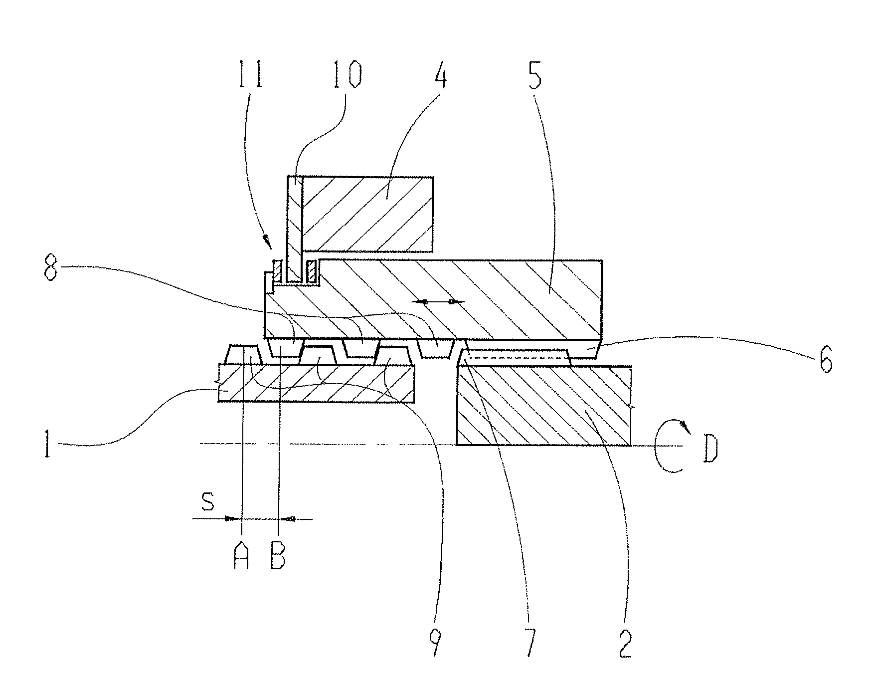
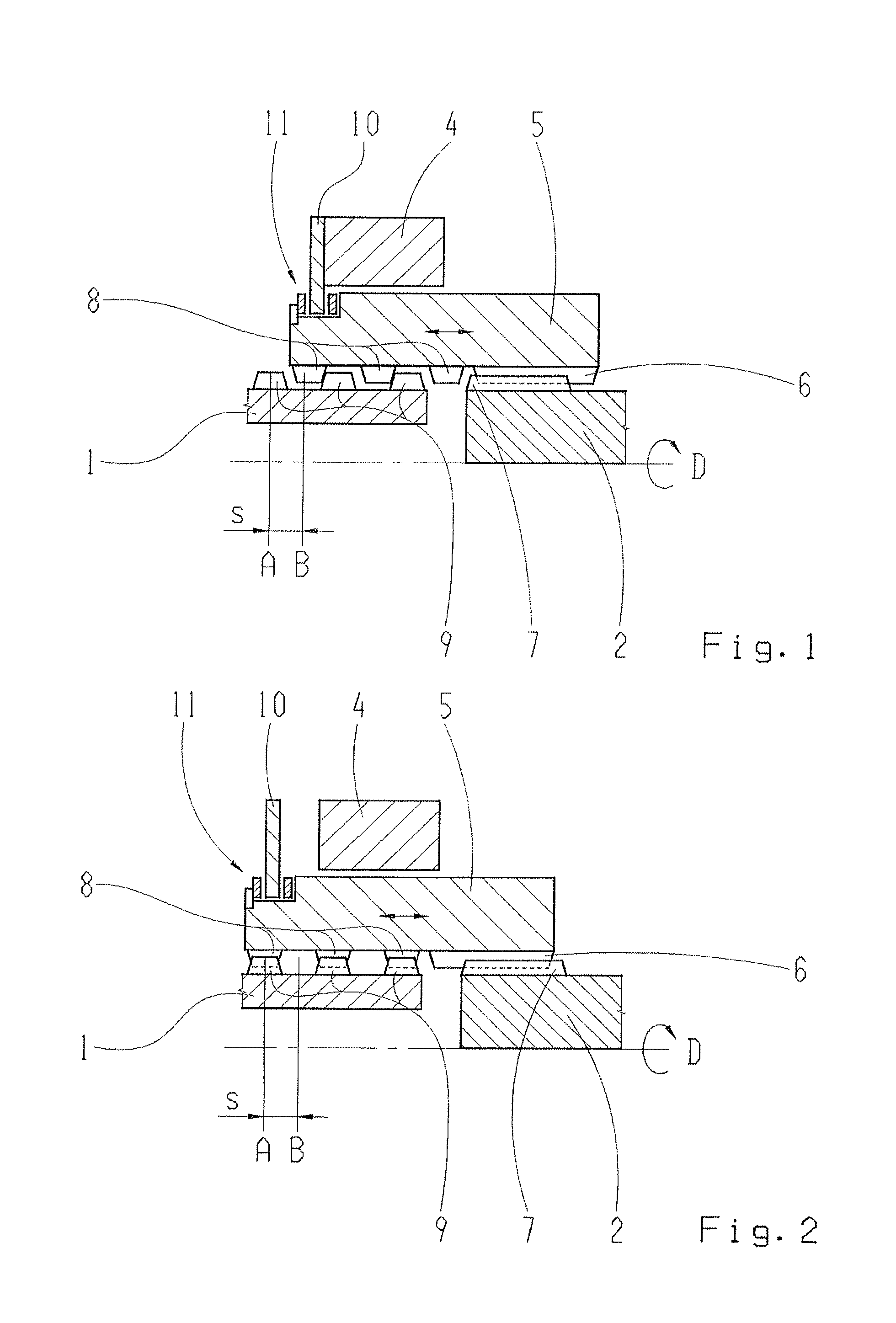
[0039]FIGS. 1 and 2 show schematic sectional representations of a single connecting device for connecting a first shaft 1 and a second shaft 2 in two different switching states. Here, in each case, the lower half of the connecting device is not shown for clarity. The same components in FIGS. 1 and 2 are assigned the same reference numbers. In FIG. 1, the shafts 1, 2 are released from each other using the connecting device, while in FIG. 2 the shafts are coupled together by means of the connecting device in order to transmit torque.

[0040]The shafts 1, 2 can rotate relative to each other and are disposed coaxially to each other about an axis of rotation D. Torque can be transmitted between the shafts 1, 2 as long as the connecting device couples the two shafts 1, 2 together. In the case shown in FIG. 1, the shafts 1, 2 are, however, released from each other using the connecting device. Thus, the shafts can rotate relative to each other, and no torque can be transmitted. The connecting...


PUM


Abstract

A connecting device for connecting first and second shafts in a rotationally fixed manner. The connecting device has a connecting element with form-locking elements that axially moves between a first axial position, to form lock the shaft via the form-locking elements, and a second axial position, to release the form lock. An actuator, when electrically energized, causes movement of the connecting element between the first and the second position. The locking elements are disposed in axially spaced first rows such that, in the first position, these rows engage with corresponding second rows of locking elements of the first shaft to achieve a form lock and couple the first and second shafts, and, in the second position, the first rows disengage from the corresponding second rows of form-locking elements of the first shaft to respectively release the first and second shafts and permit relative rotation therebetween.

Description

[0001]This application claims priority from German patent application serial no. 10 2012 210 287.6 filed Jun. 19, 2012.FIELD OF THE INVENTION[0002]The invention relates to a connecting device for a vehicle drive train for the rotationally fixed connection of a first and a second shaft that are rotatable relative to each other. Additionally the invention relates to transmission for a vehicle drive train having such a connecting device, and a method for actuating such a connecting device.BACKGROUND OF THE INVENTION[0003]Such a connecting device serves in a vehicle drive train particularly for connecting two halves of an all-wheel shaft or a wheel drive shaft, also called wheel shafts or side shafts. In a vehicle drive train having several drivable drive axles, this connecting device allows, for example, switching between an all-wheel operating mode (also called all-wheel mode, 4WD mode, AWD mode or similar), in which several or all of the drive axles of the vehicle drive train are dri...

Claims


Application Information

Patent Timeline
Patent Type & Authority Applications(United States)
IPC IPC(8): F16D11/14
CPCF16D11/14F16D11/10F16D27/004F16D27/108F16D2011/002F16D2011/006
Inventor GERAUER, GEORGBOCK, ALOIS
Owner ZF FRIEDRICHSHAFEN AG
Learn More