
Methods and systems for gain calibration of gamma ray detectors

a technology gain calibration, applied in the field of gamma ray detectors, can solve the problems of difficult to define reference crystals, difficult to apply conventional pet iterative algorithms to perform gain and energy calibration, and more complex and time-consuming processes

Active Publication Date: 2013-12-12
GENERAL ELECTRIC CO
View PDF2 Cites 40 Cited by
  • Summary
  • Abstract
  • Description
  • Claims
  • Application Information

AI Technical Summary

Benefits of technology

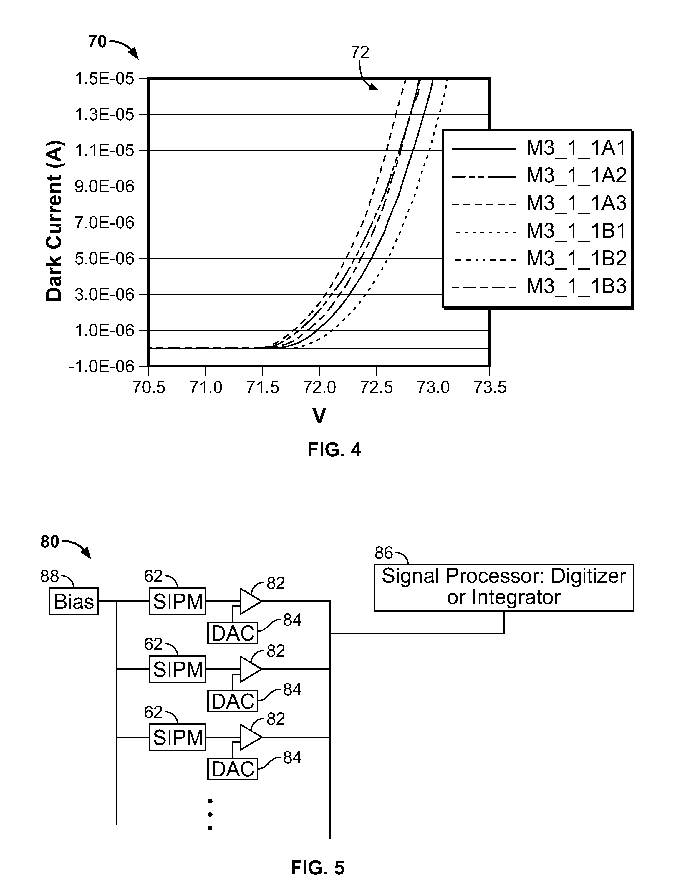
The patent text is about a method and system for calibrating a gamma ray detector. The method involves measuring signals from light sensors and using them to generate derived curves that show how the detector responds to different bias voltages. By identifying a transition point in these curves, the system can determine the breakdown voltage of the light sensors and set a new bias to prevent further damage. This approach ensures the detector operates reliably over time.

Problems solved by technology

When using a small crystal array (e.g., 4×4 array) on solid state photomultiplier based PET detectors with multi-anodes (e.g., six anodes in a 2×3 array), it is often difficult to define reference crystals as the arrangement is very sensitive to the relative positioning of crystals over the anodes.
Additionally, as the number of anodes increases, for example when six or more anodes are used, it is more difficult to apply conventional PET iterative algorithms to perform gain and energy calibration.
For example, the processes may be more complex and time consuming.
However, in some designs, for example, a light-sharing block design among multiple anodes, this is not possible.
However, when the size of the photo-sensors in these solid state photomultiplier based PET detectors increases, for example, larger than 3×3 mm2 or when generating greater than 1 million dark counts per second, these measurements also cannot be performed because the single photon pulse cannot be identified properly due to count pileup.
Thus, known processes for gain or energy calibration may not work satisfactorily for some configurations of gamma detectors, such as gamma detectors used in combination with photo-sensors, such as in solid state photomultiplier based PET detectors.

Method used


Image

  • Methods and systems for gain calibration of gamma ray detectors
  • Methods and systems for gain calibration of gamma ray detectors
  • Methods and systems for gain calibration of gamma ray detectors

Examples


Embodiment Construction

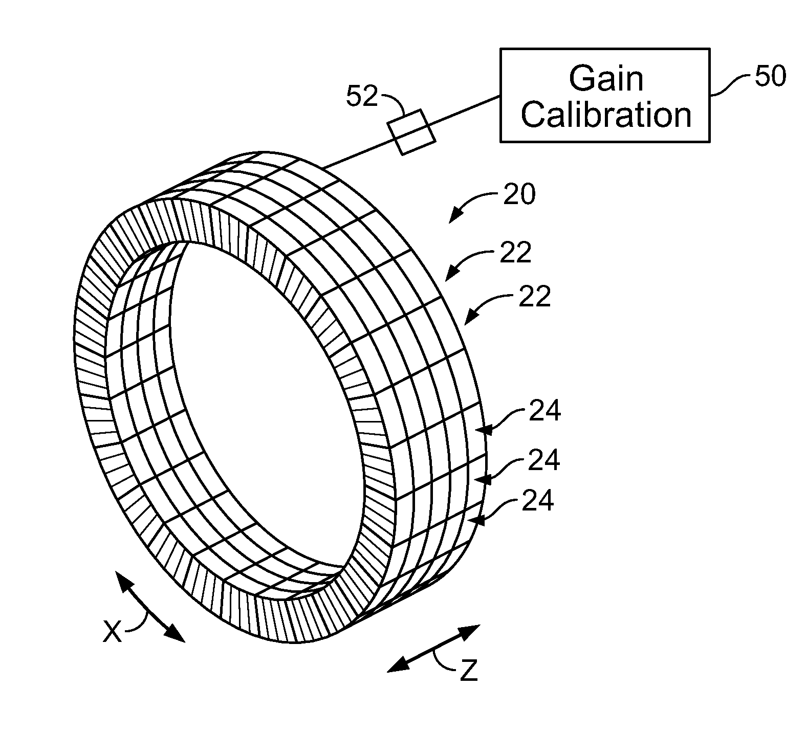
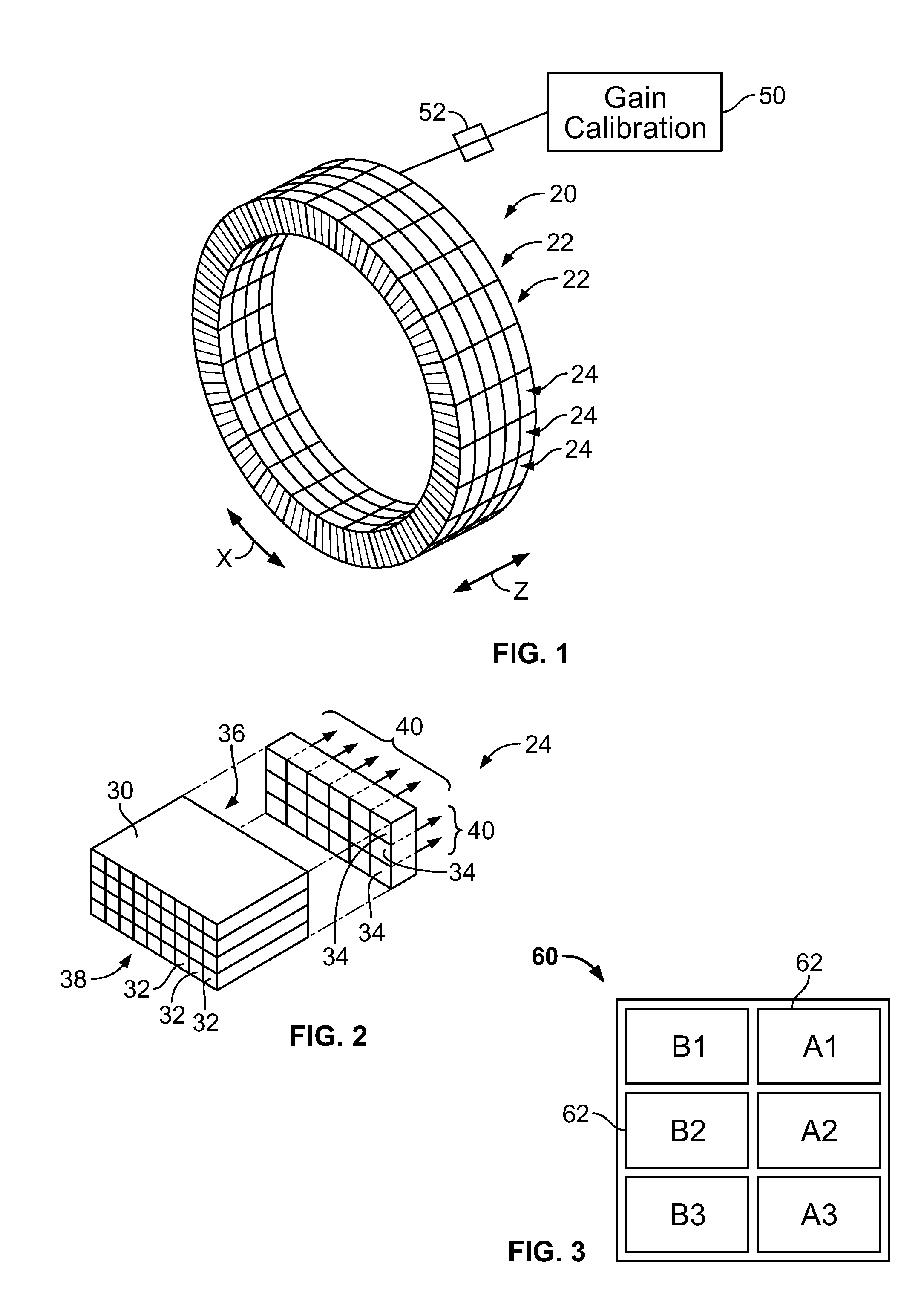
[0019]The following detailed description of certain embodiments will be better understood when read in conjunction with the appended drawings. To the extent that the figures illustrate diagrams of the functional modules of various embodiments, the functional blocks are not necessarily indicative of the division between hardware circuitry. Thus, for example, one or more of the functional blocks (e.g., processors or memories) may be implemented in a single piece of hardware (e.g., a general purpose signal processor or a block of random access memory, hard disk, or the like). Similarly, the programs may be stand-alone programs, may be incorporated as subroutines in an operating system, may be functions in an installed software package, and the like. It should be understood that the various embodiments are not limited to the arrangements and instrumentality shown in the drawings.

[0020]As used herein, an element or step recited in the singular and proceeded with the word “a” or “an” shou...


PUM


Abstract

Methods and systems for gain calibration of a gamma ray detector are provided. One method includes measuring signals generated by one or more light sensors of a gamma ray detector, generating one or more derived curves using the measured signals as a function of bias voltage and identifying a transition point in the one or more derived curves. The method also includes determining a breakdown voltage of the one or more light sensors using the identified transition point and setting a bias of the one or more light sensors based on the determined breakdown voltage.

Description

BACKGROUND OF THE INVENTION[0001]This subject matter disclosed herein relates generally to gamma ray detectors, and more particularly, to systems and methods for gain calibration of gamma ray detectors.[0002]Gamma ray detectors may be used in different applications, such as in Positron Emission Tomography (PET) systems. PET systems perform nuclear medicine imaging that generates a three-dimensional image or picture of functional processes within a body. For example, a PET system generates images that represent the distribution of positron-emitting nuclides within the body of a patient. When a positron interacts with an electron by annihilation, the entire mass of the positron-electron pair is converted into two 511 keV photons. The photons are emitted in opposite directions along a line of response. The annihilation photons are detected by detectors that are placed along the line of response on a detector ring. When these photons arrive and are detected at the detector elements at t...

Claims


Application Information

Patent Timeline
Patent Type & Authority Applications(United States)
IPC IPC(8): G01T1/20G01T1/166G01T1/24
CPCA61B6/03G01T1/208G01T1/248A61B6/585
Inventor KIM, CHANG LYONGMCDANIEL, DAVID LEOMALANEY, JAMES LINDGRENPETERSON, WILLIAM TODDTRAN, VI-HOAWAGADARIKAR, ASHWIN ASHOK
Owner GENERAL ELECTRIC CO
Learn More