
Swept turbomachinery blade

a turbomachinery and blade technology, applied in the field of turbomachinery blades, can solve the problems of pressure waves which extend along the span and degrade and achieve the effect of optimizing the efficiency of the engin

Inactive Publication Date: 2012-10-02
UNITED TECH CORP
View PDF44 Cites 42 Cited by
  • Summary
  • Abstract
  • Description
  • Claims
  • Application Information

AI Technical Summary

Benefits of technology

The invention aims to improve the efficiency of a blade cascade by reducing the aerodynamic losses caused by endwall shocks. This is achieved by minimizing the number of shocks in each interblade passage. The blade has an airfoil that is swept over at least a portion of its span, and the section of the airfoil radially coextensive with the endwall shock intercepts the endwall shock extending from the neighboring airfoil so that the endwall shock and the passage shock are coincident. The blade has a leading edge that is swept at two non-increasing or non-decreasing angles in the intermediate and tip regions, respectively. The invention has the advantage of maximizing engine efficiency.

Problems solved by technology

One disadvantage of a swept blade results from pressure waves which extend along the span of each airfoil suction surface and reflect off the surrounding case.
As a result, the working medium gas flowing into the channels encounters multiple shocks and experiences unrecoverable losses in velocity and total pressure, both of which degrade the engine's efficiency.

Method used


Image

  • Swept turbomachinery blade
  • Swept turbomachinery blade
  • Swept turbomachinery blade

Examples


Embodiment Construction

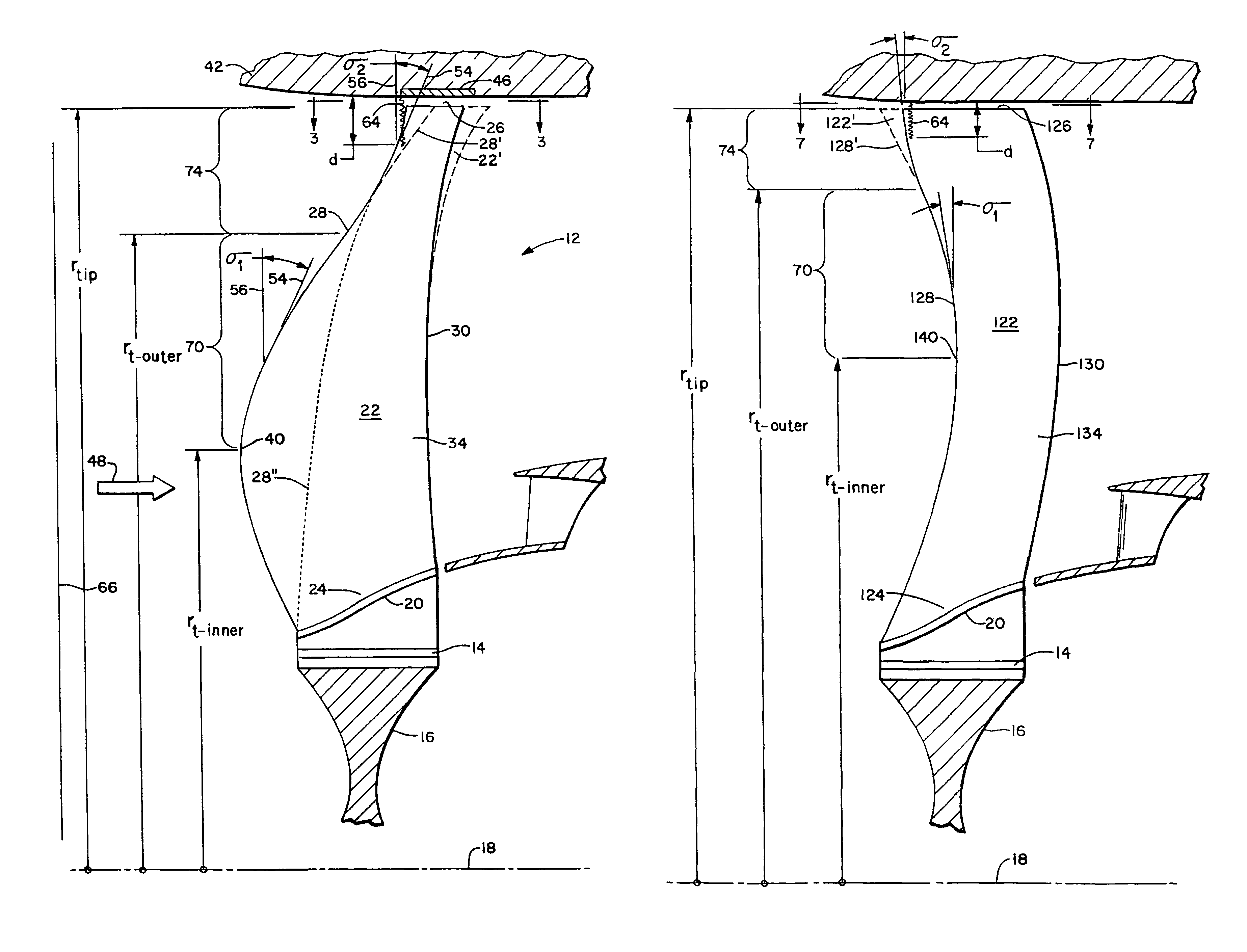
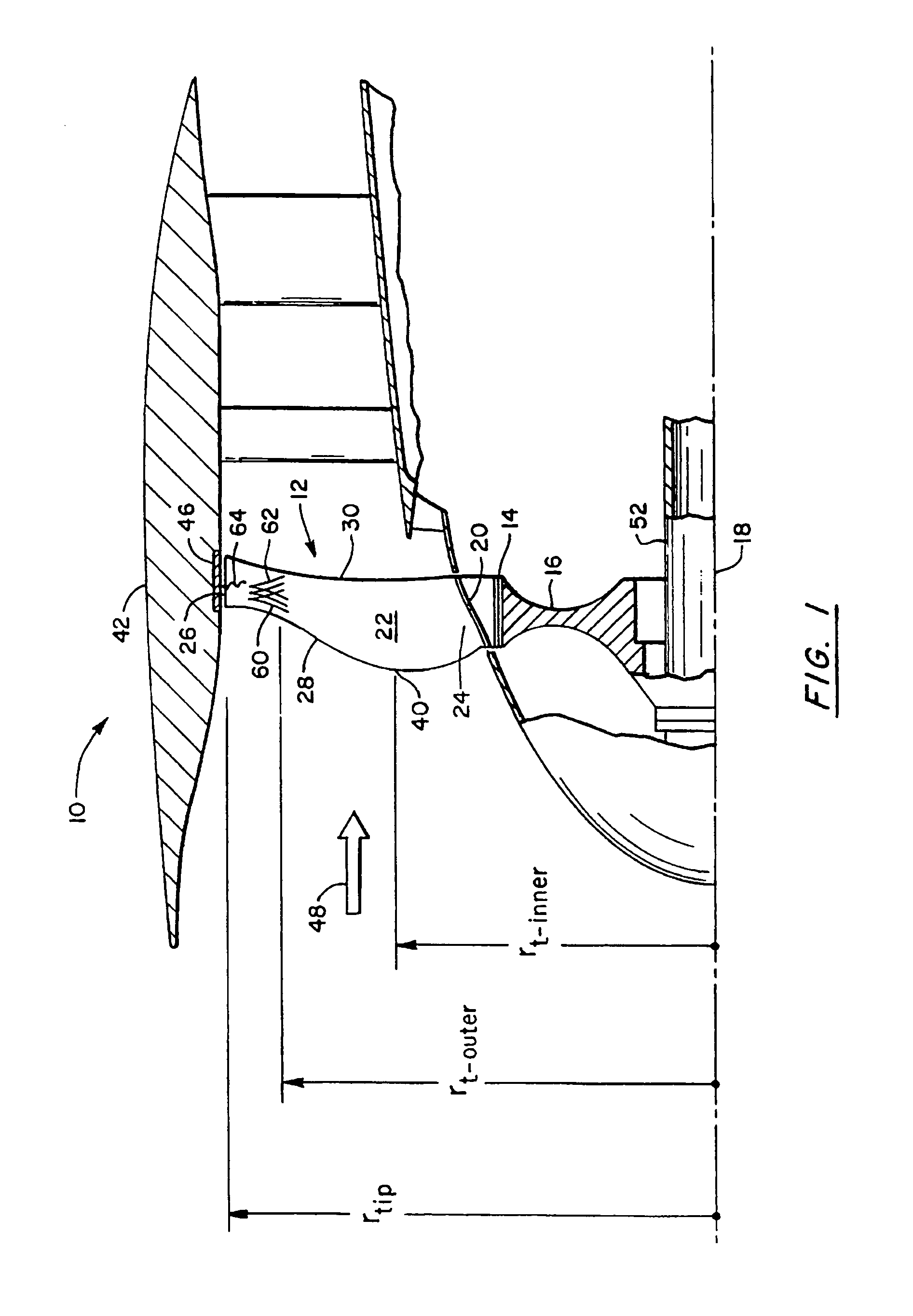
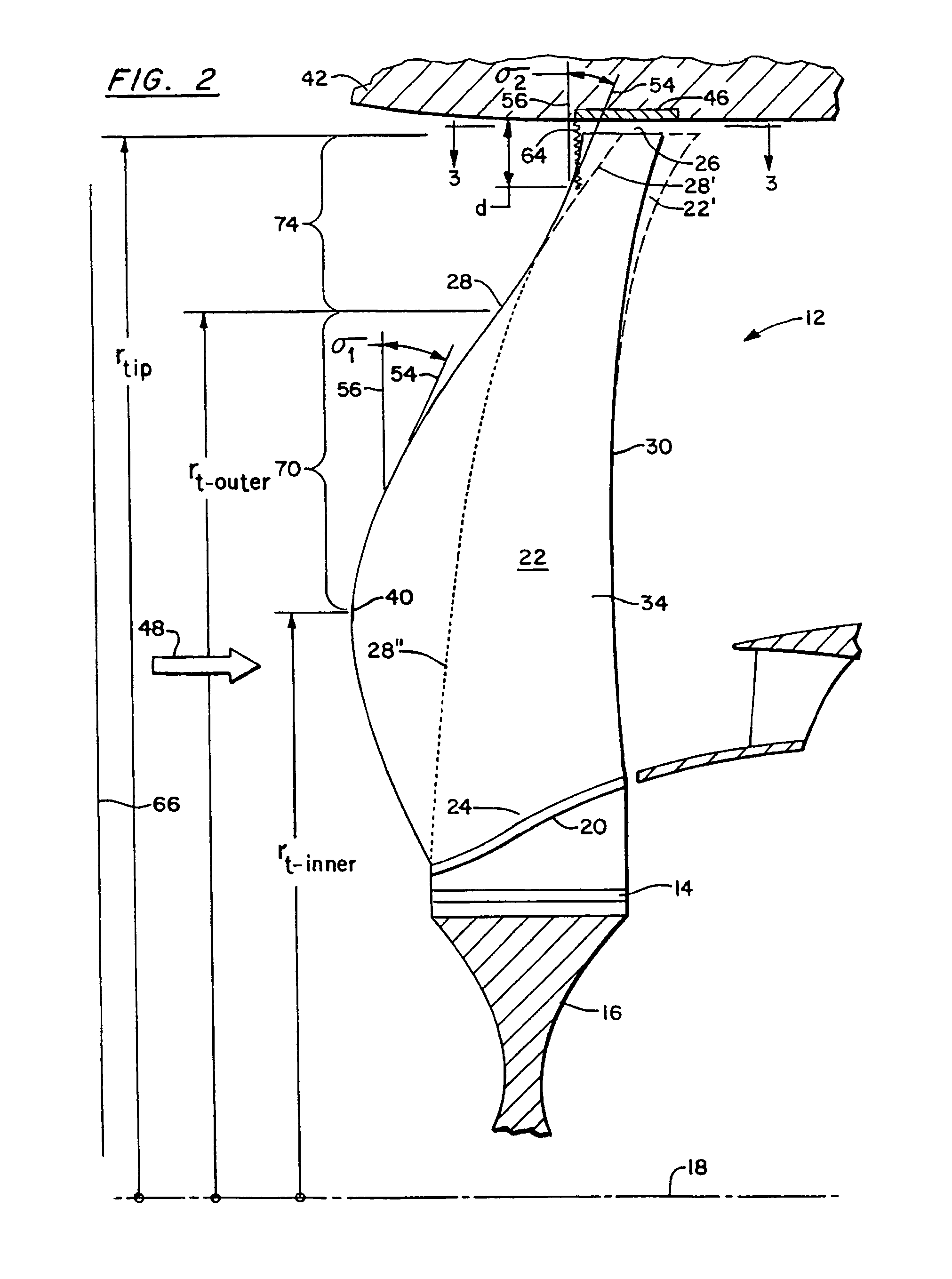
[0018]Referring to FIGS. 1-3, the forward end of a gas turbine engine includes a fan section 10 having a cascade of fan blades 12. Each blade has an attachment 14 for attaching the blade to a disk or hub 16 which is rotatable about a longitudinally extending rotational axis 18. Each blade also has a circumferentially extending platform 20 radially outward of the attachment. When installed in an engine, the platforms of neighboring blades in the cascade abut each other to form the cascade's inner flowpath boundary. An airfoil 22 extending radially outward from each platform has a root 24, a tip 26, a leading edge 28, a trailing edge 30, a pressure surface 32 and a suction surface 34. The axially forwardmost extremity of the leading edge defines an inner transition point 40 at an inner transition radius rt-inner, radially inward of the tip. The blade cascade is circumscribed by a case 42 which forms the cascade's outer flowpath boundary. The case includes a rubstrip 46 which partially...


PUM


Abstract

A swept turbomachinery blade for use in a cascade of such blades is disclosed. The blade (12) has an airfoil (22) uniquely swept so that an endwall shock (64) of limited radial extent and a passage shock (66) are coincident and a working medium (48) flowing through interblade passages (50) is subjected to a single coincident shock rather than the individual shocks. In one embodiment of the invention the forwardmost extremity of the airfoil defines an inner transition point (40) located at an inner transition radius rt-inner. The sweep angle of the airfoil is nondecreasing with increasing radius from the inner transition radius to an outer transition radius rt-outer, radially inward of the airfoil tip (26), and is nonincreasing with increasing radius between the outer transition radius and the airfoil tip.

Description

CROSS-REFERENCE TO RELATED APPLICATIONS[0001]This is a continuation of application Ser. No. 09 / 343,736, filed Jun. 30, 1999 now U.S. Pat. No. Re. 38,040, seeking reissue of U.S. Pat. No. 5,642,985, issued Jul. 1, 1997.STATEMENT REGARDING GOVERNMENT RIGHTS[0002]The government has certain rights to this invention under Department of Defense Contract No. N00140-91-C-2793.TECHNICAL FIELD[0003]This invention relates to turbomachinery blades, and particularly to blades whose airfoils are swept to minimize the adverse effects of supersonic flow of a working medium over the airfoil surfaces.BACKGROUND OF THE INVENTION[0004]Gas turbine engines employ cascades of blades to exchange energy with a compressible working medium gas that flows axially through the engine. Each blade in the cascade has an attachment which engages a slot in a rotatable hub so that the blades extend radially outward from the hub. Each blade has a radially extending airfoil, and each airfoil cooperates with the airfoils...

Claims


Application Information

Patent Timeline
Patent Type & Authority Patents(United States)
IPC IPC(8): F01D5/14F01D5/16F02K3/06F04D21/00F04D29/32F04D29/38
CPCF01D5/16F01D5/141F04D21/00F04D29/324F04D29/384F04D29/386F05D2220/327F05D2240/302F05D2250/70F05D2250/711F05D2250/712F05D2250/713
Inventor SPEAR, DAVID A.KANTOR, LEGAL REPRESENTATIVE, DENNIS N.BIEDERMAN, BRUCE P.OROSA, JOHN A.
Owner UNITED TECH CORP
Learn More