Image coding method and image decoding method
a coding method and image technology, applied in the field of image coding methods, image coding methods, image coding apparatuses, etc., to achieve the effect of keeping coding efficiency and parallel processes
- Summary
- Abstract
- Description
- Claims
- Application Information
AI Technical Summary
Benefits of technology
Problems solved by technology
Method used
Image

Examples
embodiment 1
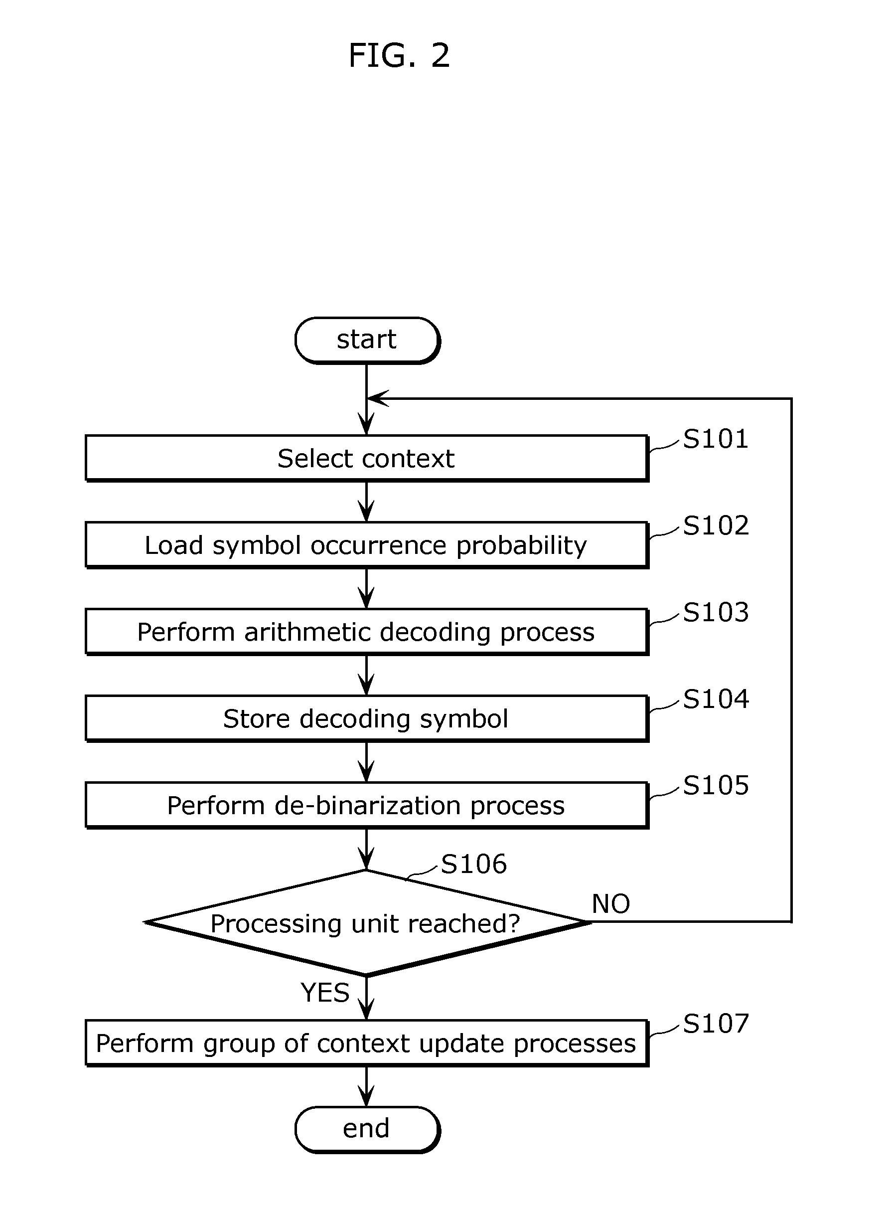
[0088]An arithmetic decoding method according to an embodiment is schematically described. The arithmetic decoding method according to this embodiment is intended to perform a group of context update processes on decoding target signals in each of processing units each obtained as a segment having a certain size. In this way, it is possible to realize parallel arithmetic decoding processes within the processing unit.
[0089]The arithmetic decoding method according to this embodiment has been schematically described above.
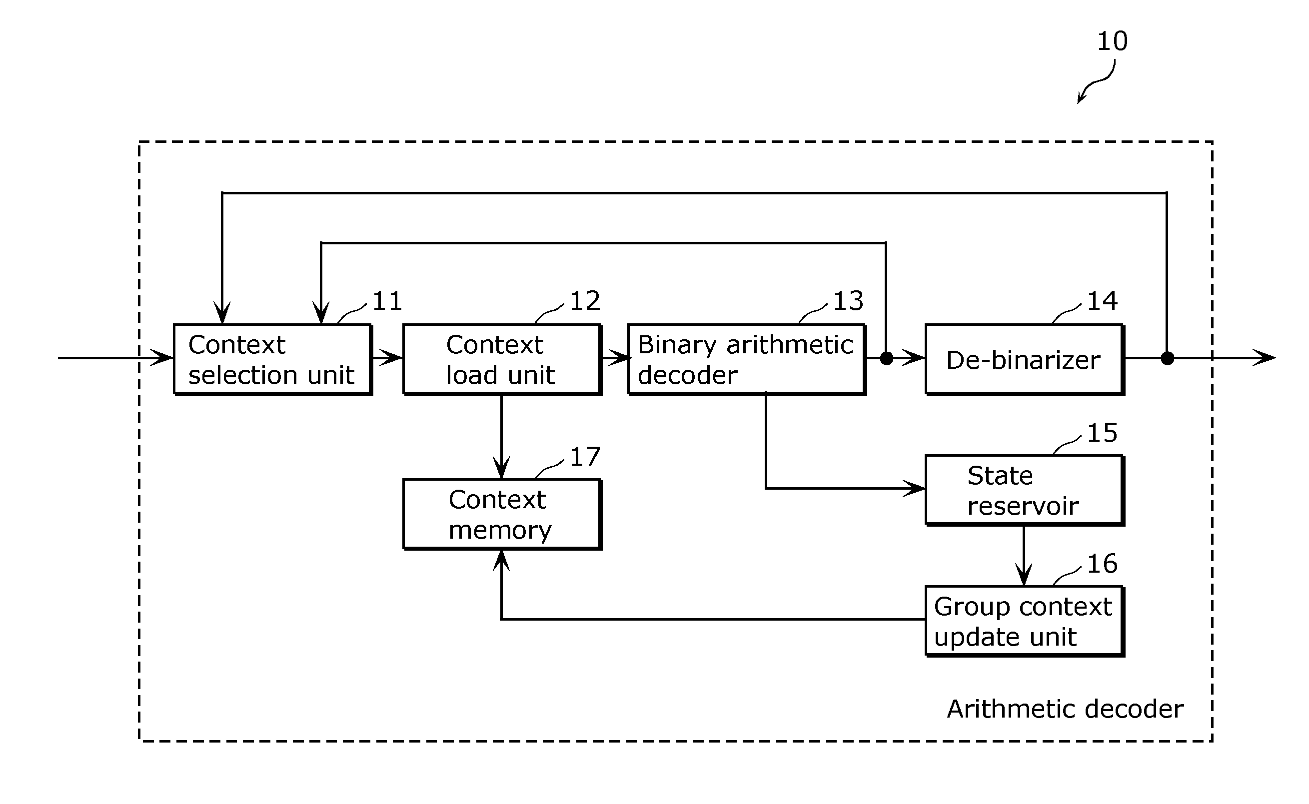
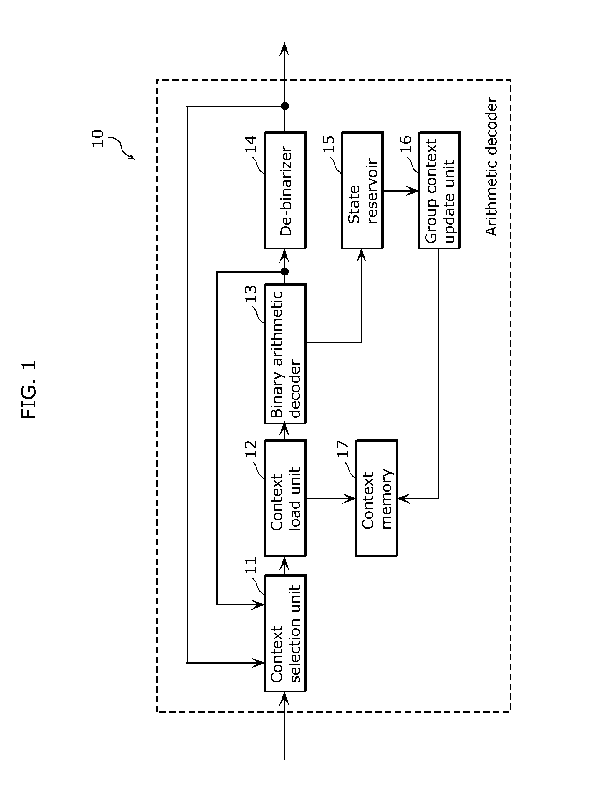
[0090]Next, a description is given of a structure of an arithmetic decoder which performs the arithmetic decoding method according to this embodiment. FIG. 1 is a block diagram showing an exemplary structure of the arithmetic decoder according to Embodiment 1. The arithmetic decoder 10 according to Embodiment 1 corresponds to a part of an image decoding apparatus 400 which decodes compression-coded image data as will be described later.
[0091]As shown in FIG. 1, the ar...
embodiment 2
[0148]An arithmetic decoding method according to an embodiment is schematically described. The arithmetic coding method according to this embodiment is intended to perform a group of context update processes on coding target signals in each of processing units each obtained as a segment having a certain size. In this way, it is possible to realize parallel arithmetic coding processes within the certain processing unit.
[0149]The arithmetic coding method according to this embodiment has been schematically described above.
[0150]Next, a description is given of a structure of an arithmetic encoder which performs the arithmetic coding method in this embodiment. FIG. 8 is a block diagram showing an exemplary structure of the arithmetic encoder according to Embodiment 2. Here, as will be described later, the arithmetic encoder 20 according to Embodiment 2 compression-codes an image signal, and corresponds to a part of an image coding apparatus 200 which outputs coded image data.
[0151]As sho...
embodiment 3
[0187]An arithmetic decoding method according to an embodiment is schematically described. The arithmetic decoding method according to this embodiment is intended to perform a group of context update processes on decoding target signals in each of processing units each obtained as a segment having a certain size. In this way, it is possible to realize parallel arithmetic decoding processes within the processing unit.
[0188]The arithmetic decoding method according to an embodiment has been schematically described above. Here, common points with respect to Embodiment 1 are not described in detail, and different points are mainly described.
[0189]Next, a description is given of a structure of an arithmetic decoder which performs the arithmetic decoding method in this embodiment. FIG. 12 is a block diagram showing an exemplary structure of the arithmetic decoder according to Embodiment 3. Here, the arithmetic decoder 30 according to Embodiment 3 corresponds to a part of an image decoding ...
PUM
 Abstract
Description
Claims
Application Information
 - R&D
- Intellectual Property
- Life Sciences
- Materials
- Tech Scout
- Unparalleled Data Quality
- Higher Quality Content
- 60% Fewer Hallucinations
Browse by: Latest US Patents, China's latest patents, Technical Efficacy Thesaurus, Application Domain, Technology Topic, Popular Technical Reports.
© 2025 PatSnap. All rights reserved.Legal|Privacy policy|Modern Slavery Act Transparency Statement|Sitemap|About US| Contact US: help@patsnap.com