Solar concentrator assembly

a technology of solar concentrator and assembly, which is applied in the direction of solar heat collector for particular environment, solar radiation concentration, photovoltaics, etc., can solve the problems of large amount of concentrated flux missing the receiver completely, photovoltaic cells are relatively expensive and sensitive, and the depletion of solar energy, etc., to achieve uniform solar flux and high solar concentratio

Inactive Publication Date: 2013-12-05
UNIVERSITI TUNKU ABDUL RAHMAN
View PDF4 Cites 5 Cited by
  • Summary
  • Abstract
  • Description
  • Claims
  • Application Information

AI Technical Summary

Benefits of technology

[0013]In the practice of the present invention, a solar concentrator assembly is provided for a solar energy system including a non-imaging dish concentrator and a photovoltaic receiver. The non-imaging dish concentrator comprises a plurality of optical assembly sets that can be arranged into any form of array. Each of the plurality of optical assembly sets comprises four flat mirrors placed together sharing one common pivot point at the centre relative to which they are inclined to create tilted angles. The tilted angles created in the four flat mirrors superpose the resultant four images of the said four flat mirrors into one. The image formed is intended to match with the square or rectangular dimension of the concentrator photovoltaic receiver thus ensuring uniform solar flux and high solar concentration ratio.

Problems solved by technology

However, the indiscriminate use of these non-renewable sources of energy has posed a threat of their depletion in the near future and hence the search for alternative sources of energy generation is sought.
However, since the photovoltaic cells are relatively expensive and sensitive, it is judicious to concentrate the solar energy with the aid of concentrators which can then be targeted to the photovoltaic cells.
However, the concentrated light image provided by a typical parabolic dish-shaped concentrator is either elliptic or circular, whereas the optimum receiving surface for many photovoltaic receivers is either rectangular or squared shape, which does not match with the profile of the concentrated light image.
However, a problem with this solution is that a substantial amount of concentrated flux may miss the receiver completely because the flux concentration image would necessarily have a greater area than the receiver surface.
Such an energy system would therefore have a lower optical efficiency corresponding to its concentrated flux losses.

Method used


Image

  • Solar concentrator assembly
  • Solar concentrator assembly
  • Solar concentrator assembly

Examples


Embodiment Construction

[0021]The present invention will now be described in detail with reference to the accompanying drawings, in which exemplary embodiments of the invention are shown. This invention may, however, be embodied in many different forms and should not be construed as limited to the embodiments set forth herein. Rather, these exemplary embodiments are provided so that this disclosure is thorough, and will fully convey the scope of the invention to those skilled in the art.

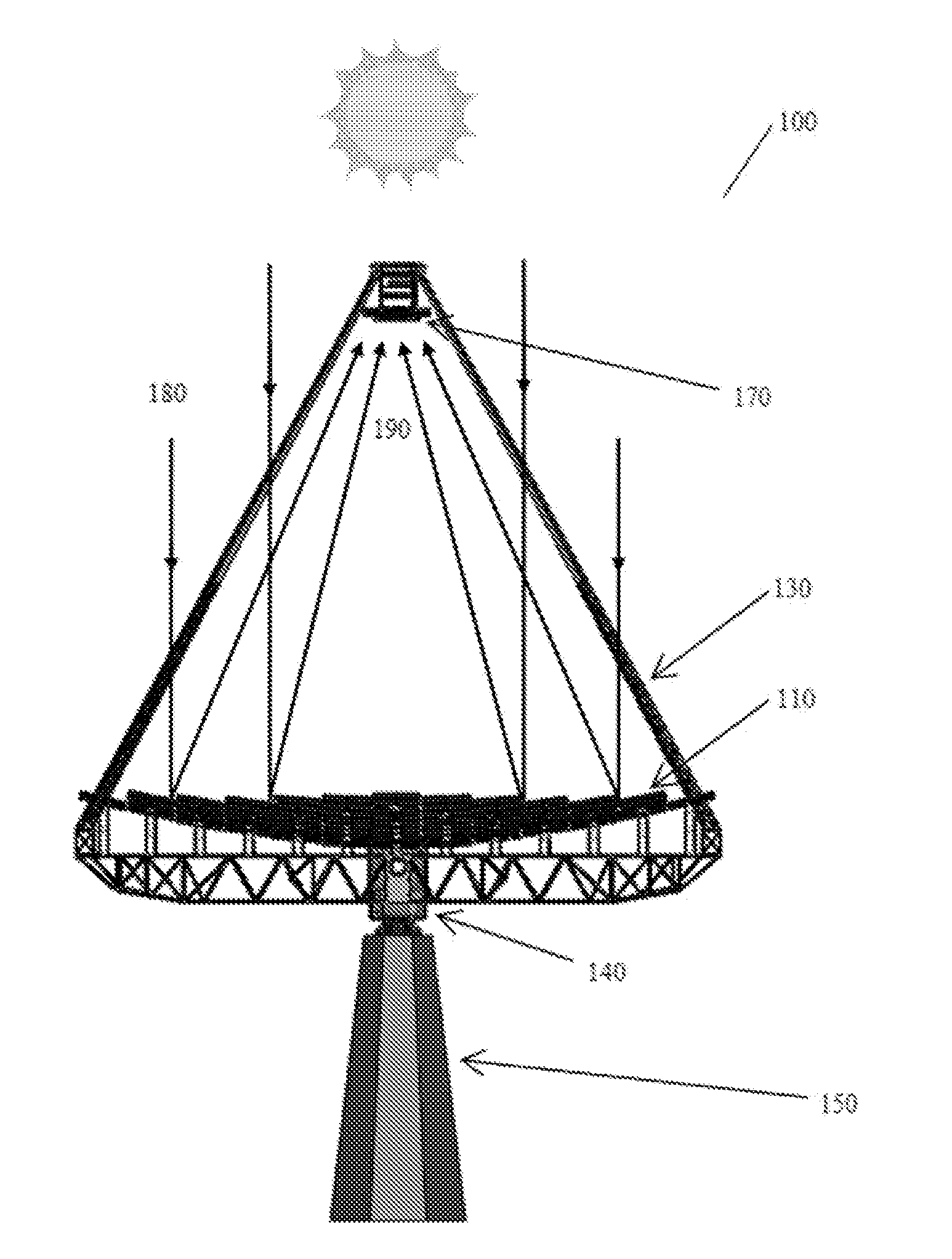
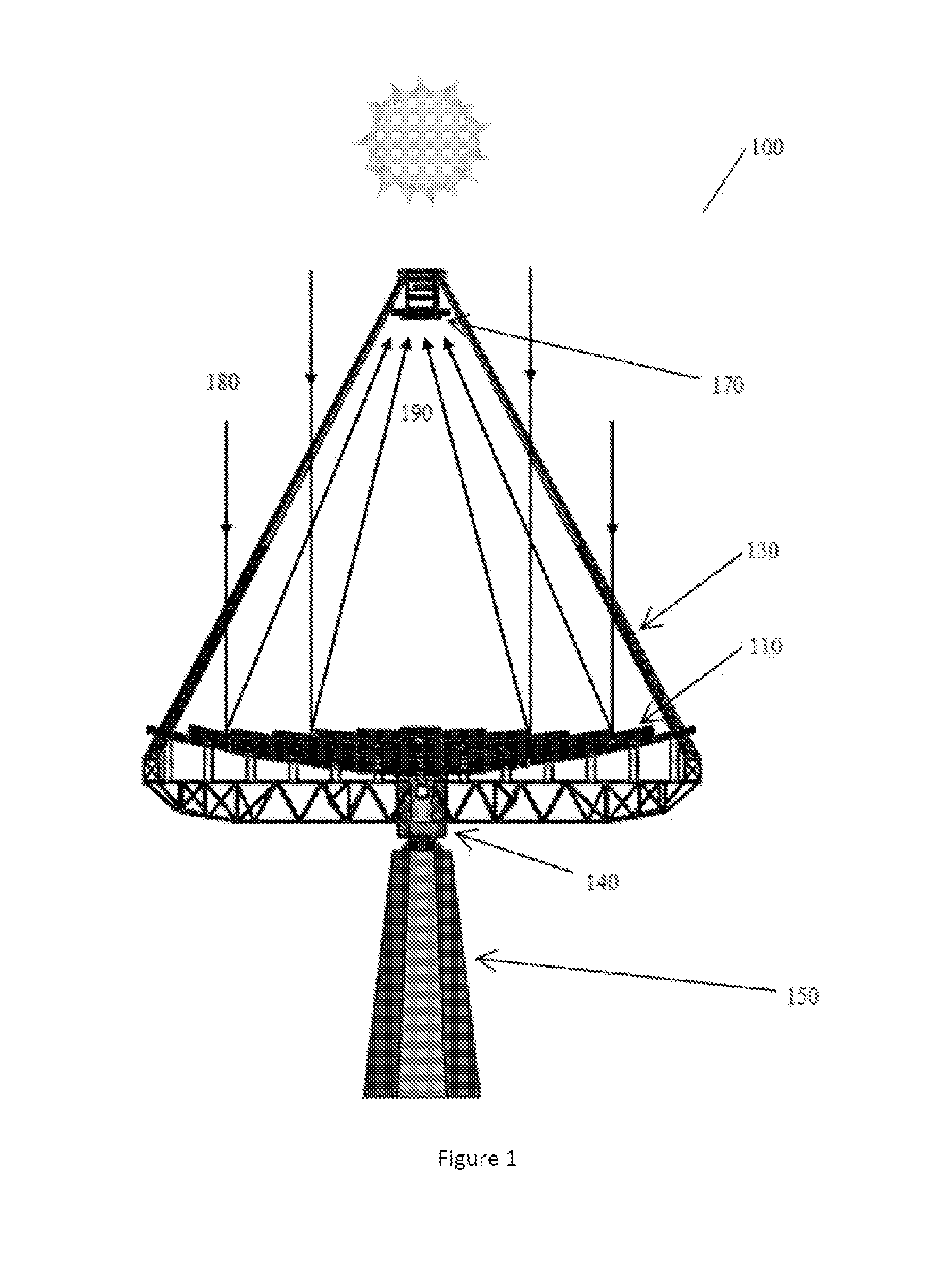
[0022]The present invention provides a solar concentrator assembly for the application of concentrator photovoltaic system. In a preferred embodiment, the present invention provides a solar concentrator assembly comprising an optically efficient, cost effective non-imaging dish concentrator.

[0023]One embodiment of the present invention provides a solar concentrator assembly comprising a non-imaging dish concentrator and a photovoltaic receiver. The non-imaging dish concentrator is specifically designed to obtain maximum opt...


PUM


Abstract

The present invention provides a solar concentrator assembly comprising a non-imaging dish concentrator and a photovoltaic receiver for the application of concentrator photovoltaic system that provides uniform solar flux, matches the square or rectangular solar images to the square or rectangular dimension of the photovoltaic receiver and produces high solar concentration ratio. The present invention also provides a solar concentrator assembly that is cost effective and has simpler mechanical structure.

Description

[0001]This application claims priority under the Paris Convention from Malaysian Patent Application No. PI2012002439 filed on May 31, 2012, which is hereby expressly incorporated by reference in its entirety for all purposes.TECHNICAL FIELD[0002]The present invention relates to a solar concentrator assembly, more particularly, relates to a non-imaging dish concentrator assembly for the application of concentrator photovoltaic system and other relevant applications that requires uniform concentrated flux.BACKGROUND OF THE INVENTION[0003]Developing countries across the globe struggle in deriving or generating the basic necessities of life for themselves. Among the other necessities, energy supply such as electricity still remains one of the major requirements in the economies of developing nations which is unattained.[0004]Over the years, people have largely relied on fossil fuels to meet their energy demands. However, the indiscriminate use of these non-renewable sources of energy ha...

Claims


Application Information

Patent Timeline
Patent Type & Authority Applications(United States)
IPC IPC(8): H01L31/052F24J2/00
CPCH01L31/0525F24J2/0015Y02E10/52H01L31/0547F24S23/71F24S2023/874F24S23/77Y02E10/40F24S20/25
Inventor CHONG, KOK KEONGWONG, CHEE WOONYEW, TIONG KEATTAN, MING HUI
Owner UNIVERSITI TUNKU ABDUL RAHMAN
Why Eureka
Try Eureka