
Method and device for monitoring the satisfactory functioning of at least one first and a second component of a vehicle drive train

a technology of vehicle drive train and component, which is applied in the direction of mechanical equipment, instruments, transportation and packaging, etc., can solve the problems of inferring the unsatisfactory functioning of at least one of the at least two components

Active Publication Date: 2013-11-21
ROBERT BOSCH GMBH
View PDF4 Cites 7 Cited by
  • Summary
  • Abstract
  • Description
  • Claims
  • Application Information

AI Technical Summary

Benefits of technology

The driving comfort and safety of this monitoring method are not disrupted because it does not unexpectedly increase or decrease the amount of torque. This monitoring method also prevents disruptions in the vehicle's drive train caused by unsatisfactory functioning of components. Additionally, this method compensates for unsatisfactory functionality of components by changing their actuation. This reduces the impact on the driveshaft and enables further operation of the vehicle drive train, even in the case of unsatisfactory functionality. Overall, this monitoring method improves the vehicle's driving performance and prevents malfunctions during operation.

Problems solved by technology

In this way, unsatisfactory functioning of at least one of the two components can be inferred on the basis of an unsatisfactory change in rotational speed or acceleration of the rotational speed, for example of a driveshaft in the drive train.
If the effects of the first and second components do not cancel one another out on the basis of the two test signals, unsatisfactory functioning of at least one of the at least two components is inferred.

Method used

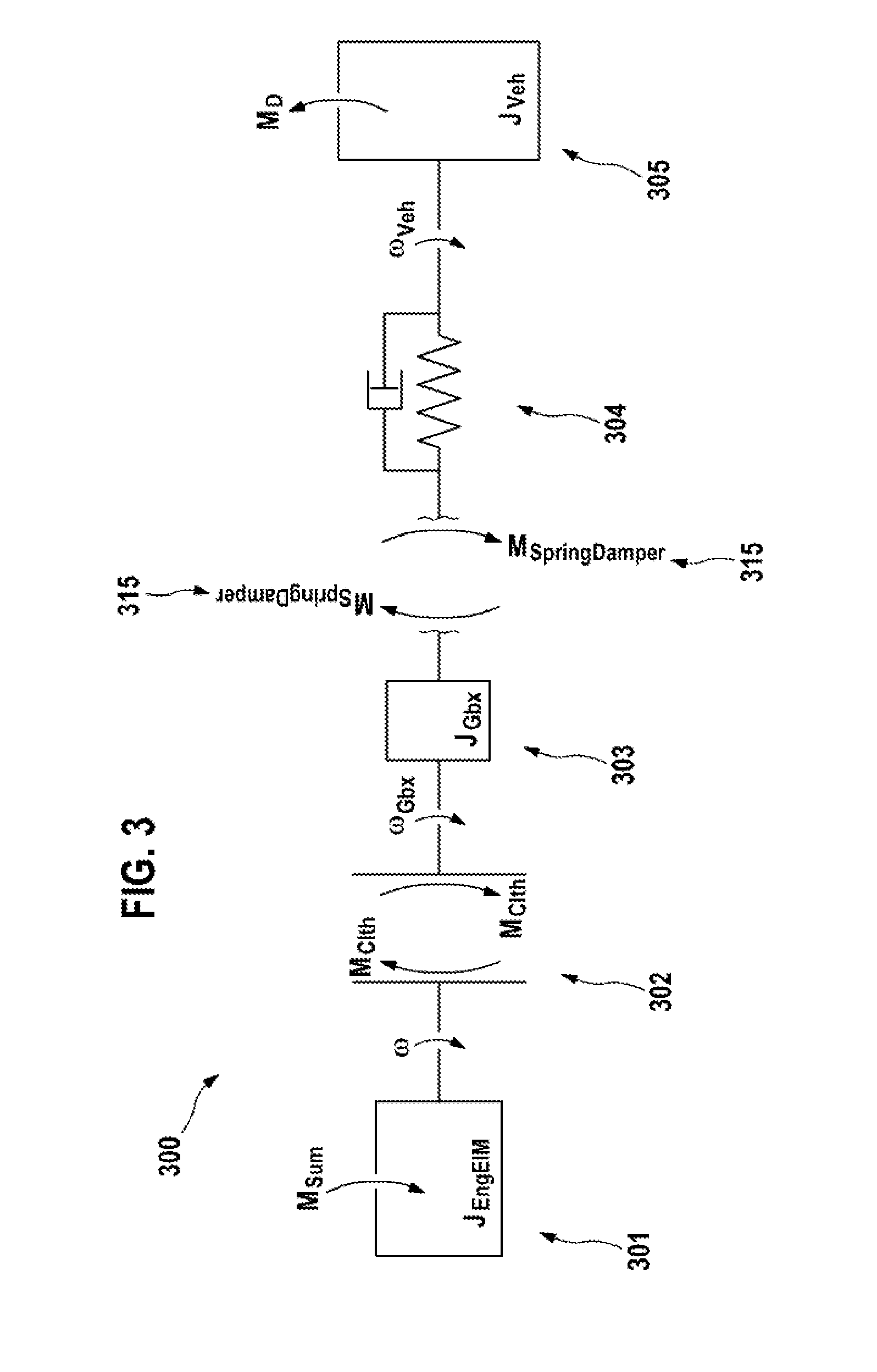

Image

  • Method and device for monitoring the satisfactory functioning of at least one first and a second component of a vehicle drive train
  • Method and device for monitoring the satisfactory functioning of at least one first and a second component of a vehicle drive train
  • Method and device for monitoring the satisfactory functioning of at least one first and a second component of a vehicle drive train

Examples


Embodiment Construction

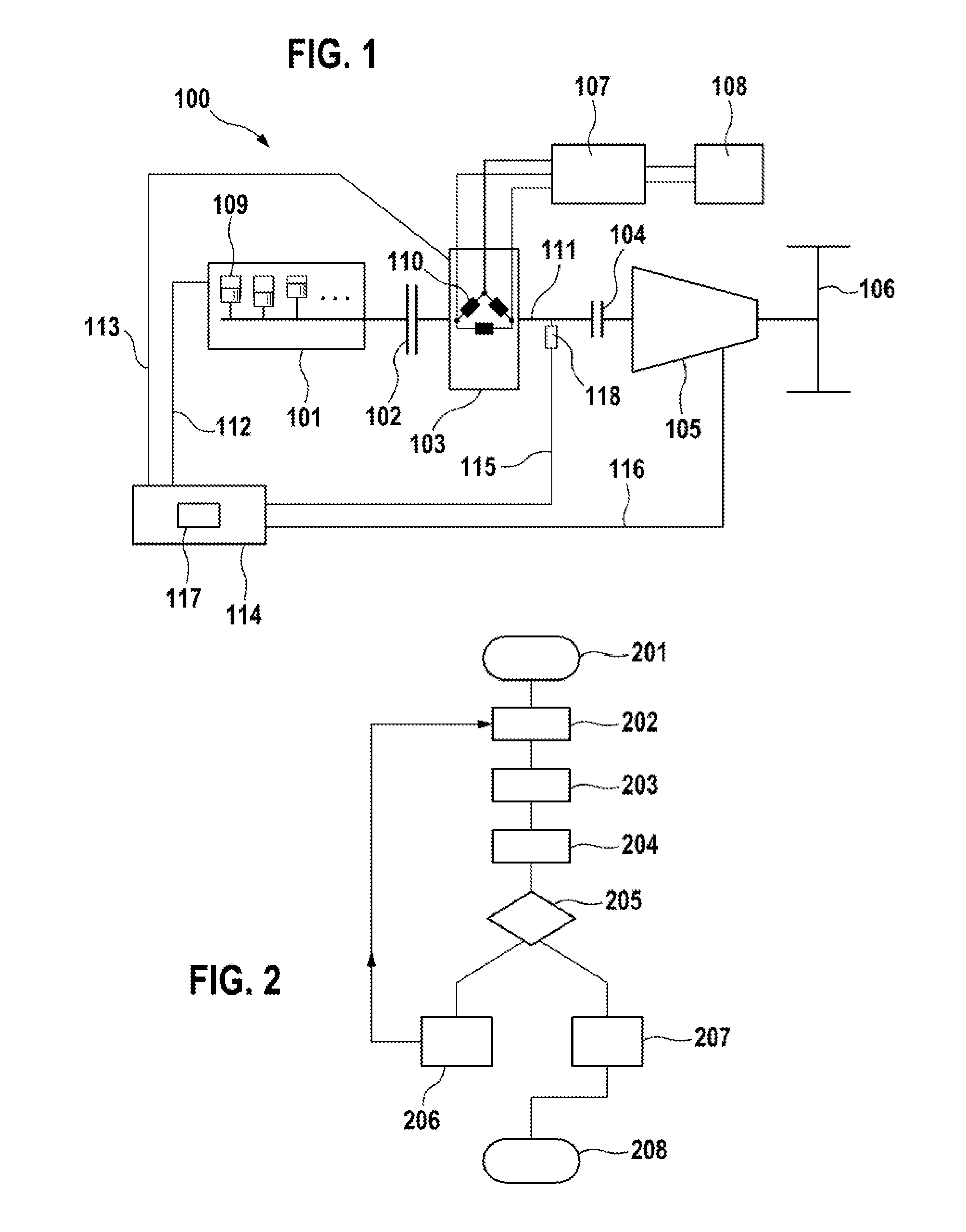
[0026]FIG. 1 shows a basic illustration of a vehicle drive train 100 of a vehicle with a hybrid drive. A first drive assembly, specifically an internal combustion engine 101, can be coupled via a clutch 102 to a second drive assembly, specifically an electric machine 103. The two drive assemblies act on a driveshaft 111 when the clutch 102 is closed. The driveshaft 111 can be coupled via a further transmitting element 104, for example a torque converter or a friction clutch, to a transmission 105. On the output side, the transmission 105 is mechanically coupled to a drive axle with drive wheels 106. A voltage source 108, for example a battery, makes available electrical energy to the electric machine 103 via an inverter 107. For this purpose, the inverter 107 converts the direct current of the voltage source 108 into three-phase current which flows in a phase-shifted fashion through each of the individual windings 110 of the electric machine 103, wherein the individual windings 110 ...


PUM


Abstract

The invention relates to a method for monitoring the proper functioning of at least one first and a second component (109, 110) of a vehicle drive train (100). The first and the second component (109, 110) each have an effect on the torque applied to the driveshaft (111) and are controlled for this purpose by a test signal (112, 113). The test signals (112, 113) are predetermined such that the effects of the first and the second component (109, 110) onto the torque applied to the driveshaft (111) cancel each other out if the first and the second component (109, 110) function properly. When the components (109, 110) function properly, the traveling comfort is not disturbed by an unexpected torque increase or torque decrease during the carrying out of this method. Any perturbation of the vehicle drive train (100) is therefore also avoided.

Description

BACKGROUND OF THE INVENTION[0001]Actuating an internal combustion engine with an interference signal and evaluating the reaction of the internal combustion engine with the purpose of detecting the operating state of the internal combustion engine is known from the German patent application with the file reference 102008041108.6.[0002]Vehicle drive trains are usually not equipped with sensors which permit direct measurement of currently generated drive torques. Fault-free operation of a drive assembly or satisfactory generation of torque therefore cannot be determined directly. In the case of internal combustion engines, satisfactory combustion, in particular at a low load, can only be detected with difficulty. Available measurement signals for internal combustion engines are usually not sufficient. In the case of unsatisfactory combustion there is a risk of unburnt fuel passing into the oil circuit or the exhaust section and causing damage or a fire, for example during relatively lo...

Claims


Application Information

Patent Timeline
IPC IPC(8): G06F11/30
CPCG06F11/3065B60K6/48B60W10/06B60W10/08B60W20/00B60W20/50B60W50/0205B60W2050/0041B60W2050/0088Y02T10/40Y02T10/62B60W2050/021G06C23/02G07C5/02G07C5/0808
Inventor FALKENSTEIN, JENS-WERNER
Owner ROBERT BOSCH GMBH
Learn More