
Light source apparatus and image projection apparatus

a technology of light source apparatus and image projection apparatus, which is applied in the direction of lighting and heating apparatus, point-like light source, instruments, etc., can solve the problems of difficult dissipation of heat from the inner laser diode, inconvenient cooling of light source, and insufficient light intensity

Inactive Publication Date: 2013-11-21
RICOH KK
View PDF10 Cites 30 Cited by
  • Summary
  • Abstract
  • Description
  • Claims
  • Application Information

AI Technical Summary

Benefits of technology

The patent aims to address the issue of unstable output light intensity caused by the cooling performance of light sources at different locations when using a reflection mirror to synthesize light beams. Additionally, using multiple mirrors for synthesizing light beams can make it difficult to design and adjust the mirrors, and requires a space for disposing them in a step-like structure which may not be compact. The technical effects of the patent propose to solve these issues.

Problems solved by technology

When the laser diode is employed as the light source for the image projection apparatuses, how to secure sufficient light intensity becomes an issue.
When a large number of light sources (e.g., laser diodes) are densely disposed on a plane, how to cool the light sources efficiently becomes an issue.
However, dissipation of heat of the inner laser diodes becomes difficult compared to the outer laser diodes, thereby requiring a cooling device having greater cooling capacity than necessary.
Inadequate cooling can destabilize light emission of the laser diodes and shorten the lifetime of the laser diodes.
However, as the pitch increases so too does the size of the apparatus, as does a cross-section area of a light beam flux exiting from the light sources thereby necessitating a larger lens to condense the light beam flux.
A light intensity equalizing unit such as a rod integrator can be used to equalize light intensity, but if an incidence angle becomes too great a feasible optical system may not be achievable.
Further, if a light emission area increases, the etendue increases and a ratio of light not used for projection increases, i.e., light-use efficiency deteriorates.
When high intensity light sources are disposed two dimensionally, a cooling performance of the light sources at the outer side and a cooling performance of the light sources at the inner side surrounded by the outer side become different, by which the output light intensity may become unstable.
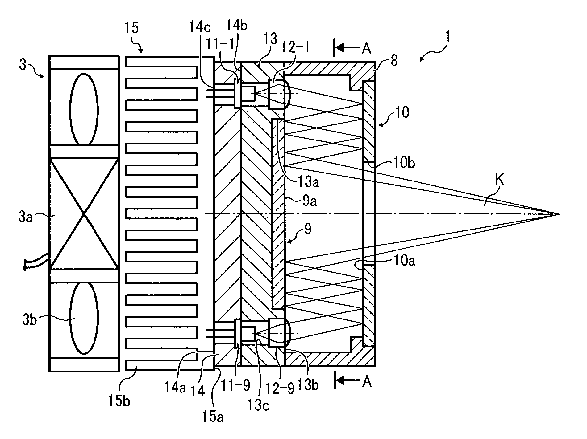
Further, when a plurality of mirrors is used for synthesizing light beams, it becomes difficult to design positions of each of mirrors and to adjust each of mirrors, and a space for disposing the plurality of mirrors as a step-like structure is required, which may not good for achieving a compact apparatus.

Method used


Image

  • Light source apparatus and image projection apparatus
  • Light source apparatus and image projection apparatus
  • Light source apparatus and image projection apparatus

Examples


Embodiment Construction

[0027]A description is now given of exemplary embodiments of the present invention. It should be noted that although such terms as first, second, etc. may be used herein to describe various elements, components, regions, layers and / or sections, it should be understood that such elements, components, regions, layers and / or sections are not limited thereby because such terms are relative, that is, used only to distinguish one element, component, region, layer or section from another region, layer or section. Thus, for example, a first element, component, region, layer or section discussed below could be termed a second element, component, region, layer or section without departing from the teachings of the present invention.

[0028]In addition, it should be noted that the terminology used herein is for the purpose of describing particular embodiments only and is not intended to be limiting of the present invention. Thus, for example, as used herein, the singular forms “a”, “an” and “the...


PUM


Abstract

A light source apparatus includes a first reflector having a first reflection face; a second reflector having a second reflection face, the first reflection face of the first reflector and the second reflection face of the second reflector disposed opposite each other; and a plurality of light sources being disposed around a periphery of the second reflector. Light beams emitted from the plurality of light sources reflect on the first reflector and then reflect on the second reflector.

Description

[0001]This application claims priority pursuant to 35 U.S.C. §119 to Japanese Patent Application No. 2012-114923, filed on May 18, 2012 and No.2013-048137, filed on Mar. 11, 2013 in the Japan Patent Office, the disclosures of which are incorporated by reference herein in their entirety.BACKGROUND[0002]1. Technical Field[0003]The present invention relates to a light source apparatus having a plurality of light sources, and an image projection apparatus employing the light source apparatus.[0004]2. Background Art[0005]Screen images of personal computers, video images, and image data stored in memory cards can be transmitted to image projection apparatuses known as projectors that can project images onto a screen. In the projector, light emitted from a light source is focused on a micro mirror display device known as a digital micro mirror device (DMD), or a liquid crystal plate, and then images are displayed as color images on the screen.[0006]In the projector, a high intensity discha...

Claims


Application Information

Patent Timeline
IPC IPC(8): G03B21/20F21V7/00F21V13/04F21V29/02F21V29/00
CPCG03B21/2066F21V29/02F21V29/22F21V13/04F21V7/0033G03B21/16G03B21/2013G03B21/2033F21V29/60
Inventor NISHIMORI, TAKEHIROFUJITA, KAZUHIROMURAI, TOSHIHARUMAEDA, IKUOTAKAHASHI, TATSUYA
Owner RICOH KK
Learn More