Eureka AIR delivers breakthrough ideas for toughest innovation challenges, trusted by R&D personnel around the world.

Market-Based Virtual Machine Allocation

a virtual machine and market technology, applied in the field of cloud computing, can solve the problems of limited and less reliable physical resources, cloud-based systems, and difficult to reach optimal (or near-optimal) decisions

Inactive Publication Date: 2013-11-14
RACKSPACE US
View PDF16 Cites 335 Cited by
  • Summary
  • Abstract
  • Description
  • Claims
  • Application Information

AI Technical Summary

Benefits of technology

The patent is about a cloud computing system that has many computers that can run virtual machines. Each computer has its own optimizing agent that decides how to use the computer's resources. The computer also has monitors that collect information about the computer. This helps the overall system work better.

Problems solved by technology

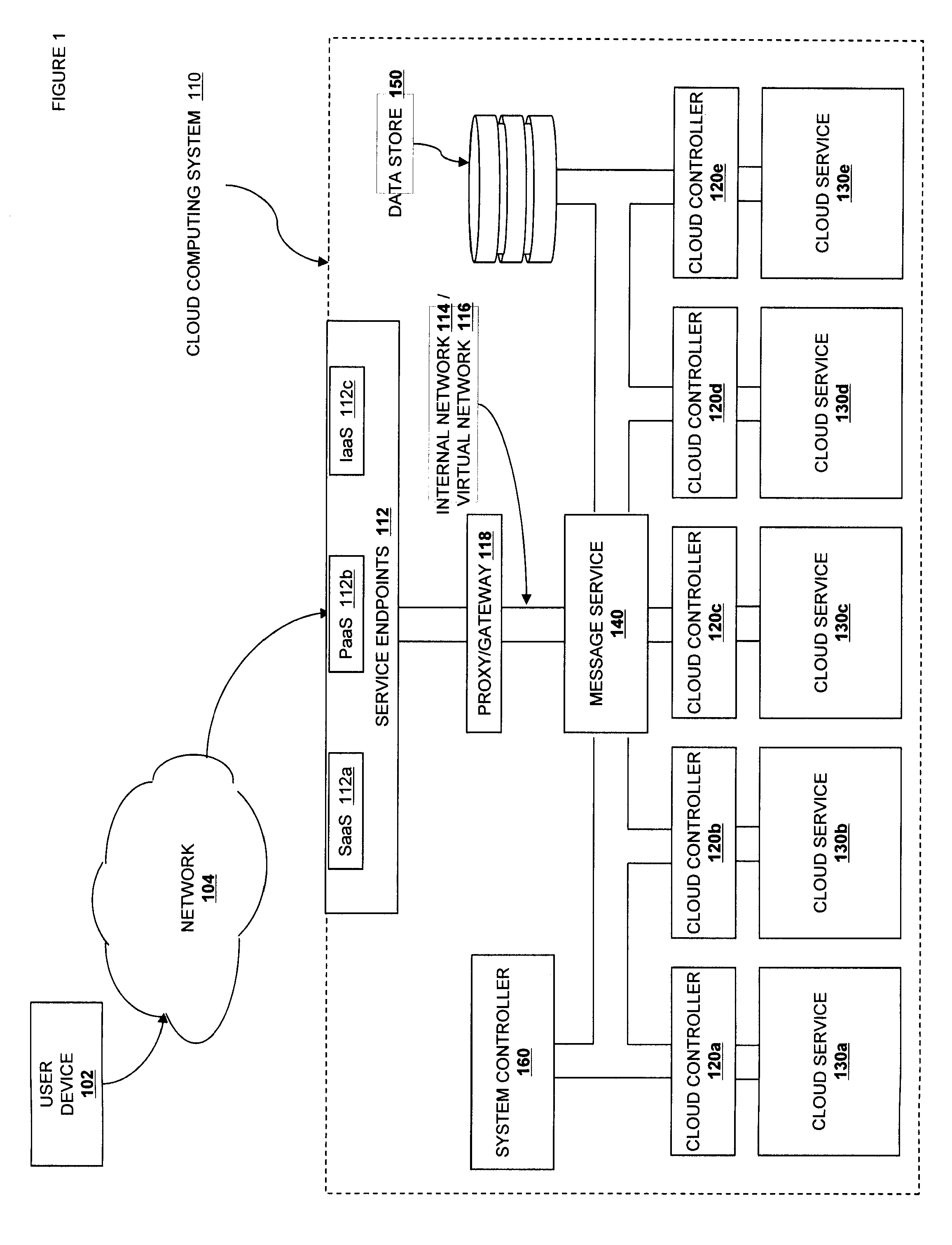
As a result of the utility model of cloud computing, there are a number of aspects of cloud-based systems that can present challenges to existing application infrastructure.
Second, network access is necessary.
Further, the cloud itself as well as applications that use cloud computing resources must be prepared for impermanent, fungible resources; application or cloud state must be explicitly managed because there is no guaranteed permanence of the infrastructure.
Maintaining the reliable flow and delivery of dynamically changing computational resources on top of a pool of limited and less-reliable physical servers provides unique challenges.
Second is the scale of cloud-based systems.
Because of the size of the optimization problem, it is difficult to reach optimal (or near-optimal) decisions when faced with substantial load.
Further complicating the issue, most cloud systems assume a relatively homogenous pool of underlying computing resources, on top of which a homogenous pool of virtualized resources is instantiated.
The hardware components of these servers can vary significantly, causing instance performance variances based on the capabilities of the host compute node for a particular instance.

Method used


Image

  • Market-Based Virtual Machine Allocation
  • Market-Based Virtual Machine Allocation
  • Market-Based Virtual Machine Allocation

Examples


third embodiment

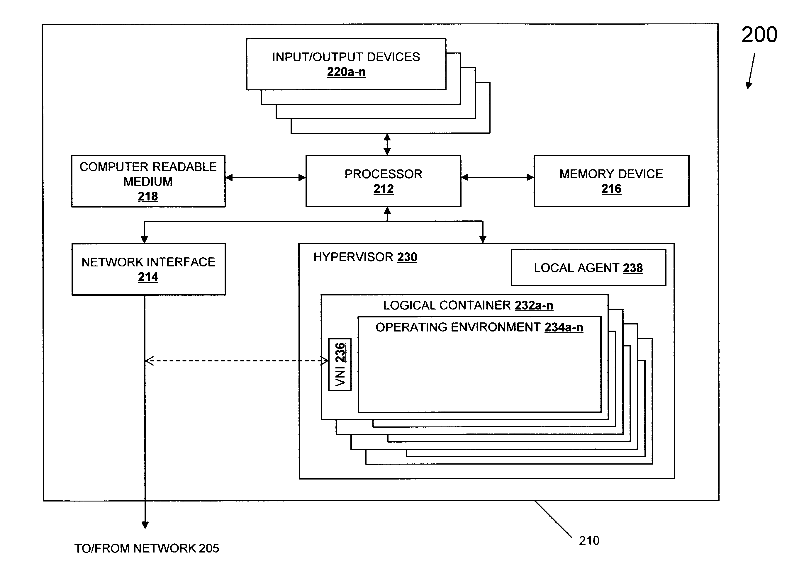
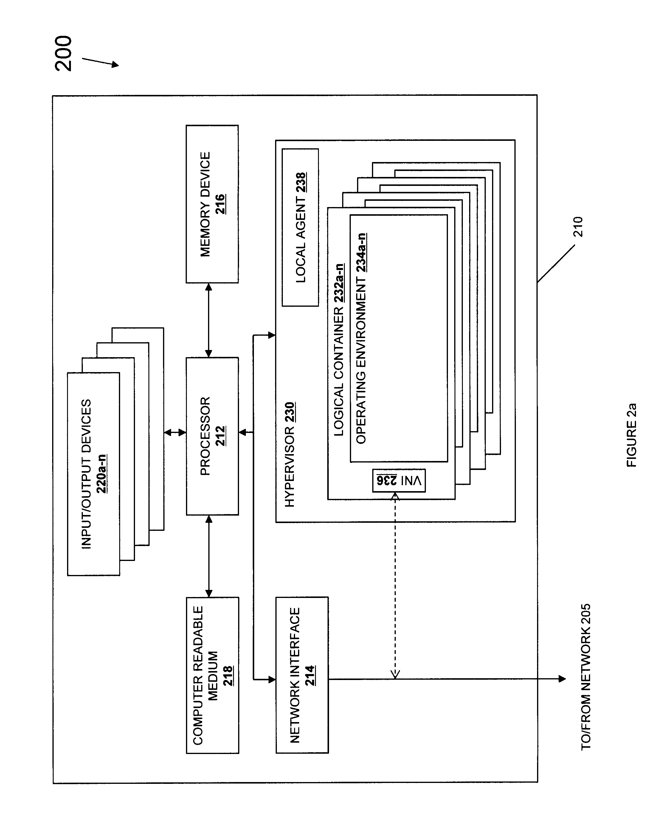
[0074]In one embodiment, the local agent 238 is implemented as part of the hypervisor or as a process running on a hypervisor-enabled operating system. In another embodiment, the local agent 238 is implemented as an operating environment 234 running in one of the logical containers 232. A third embodiment implements the local agent as an independent co-processor coupled to and in communication with the machine 210, as described elsewhere in this specification. It is also contemplated that different implementations may use one or more of these as a set of interoperating but discrete components, some or all of which may be implemented as software programs, with different portions implemented in hardware, in software, and in various operating environments to match different latency and computing needs. It is expected that in some embodiments, the local agent 238 will have an integrated battery and will be able to spend an extended period of time without drawing current. Various embodim...

second embodiment

[0081]The IPMI subsystem 240 further includes other types of busses, including System Management (SMBus) 262, LPC bus 264, and other types of busses 268 as known in the art and provided by various system integrators for use with BMC 250. By use of these busses, the BMC can interact with or monitor different hardware subsystems within the information processing system 210, including the Southbridge 252, the network interface 214, the computer readable medium 218, the processor 212, the memory device 216, the power supply 254, the chipset 256 and the GPU or other card 258. In one embodiment, each of these subsystems has integrated testing and monitoring functionality, and exposes that directly to the BMC 250. In a second embodiment, there are one or more sensors arrayed on the motherboard or within the chassis of the information processing system 210 or a larger rack or computing enclosure. For example, SMART sensors are used in one embodiment to provide hard drive related information...

first embodiment

[0191]With reference now to FIG. 9a, illustrated is a system 900 that is similar to the system 800 of FIG. 8 but also includes the compute cluster 676b. The compute cluster 676b includes a plurality of information processing systems (IPS) 910a-910n that are similar to the information processing systems 810a-810n described in association with FIG. 8. The IPSes may be homogeneous or non-homogeneous depending on the computer hardware utilized to form the compute cluster 676b. The information processing systems 910a-910n respectively include local agents 914a-914n that are operable to gather metadata about and perform local computation about the information processing systems and the VM instances executing thereon. As shown in the illustrated embodiment of FIG. 9, the system 900 also includes a cluster monitor 940 that is operable to oversee operation of the compute cluster 676b and includes a registry 942 for the storage of metadata received from the monitors 914a-914n. The second clus...


PUM


Abstract

A cloud computing system management system including a plurality of computing devices configured to host virtual machine instances, each computing device in the plurality of computing devices including a local agent that continuously evaluates the observed load relative to a utility maximization function. If observed load is higher than a calculated optimal level, individual loading processes are offered for “sale” via a market scheduler. If observed load is lower than a calculated optimal level, then available capacity is offered as a bid via the market scheduler. The market scheduler matches bids with available processes and coordinates the transfer of load from the selling device to the buying device. The offered prices and utility maximization functions can be employed to optimize the performance of the cloud system as a whole.

Description

[0001]This application is a continuation-in-part of application Ser. No. 13 / 467,686, filed May 9, 2012, entitled “Wake-on-LAN and Instantiate-on-LAN in a Cloud Computing System,” and is related to application Ser. No. 13 / 491,866, filed Jun. 8, 2012, entitled “System and Method for Metadata Discovery and Metadata-Aware Scheduling,” which are incorporated by reference in their entirety herein.BACKGROUND[0002]The present disclosure relates generally to cloud computing, and more particularly to a more efficient and scalable method for utilizing the scarce resources in a cloud computing system.[0003]Cloud computing services can provide computational capacity, data access, networking / routing and storage services via a large pool of shared resources operated by a cloud computing provider. Because the computing resources are delivered over a network, cloud computing is location-independent computing, with all resources being provided to end-users on demand with control of the physical resou...

Claims


Application Information

Patent Timeline
Patent Type & Authority Applications(United States)
IPC IPC(8): H04L12/26
CPCH04L43/0817G06F9/45558G06F2009/4557G06F9/5088G06F2209/5022G06Q30/08G06F9/06G06F9/44H04L67/51H04L41/5054H04L47/783H04L67/10
Inventor MICK, JASONBRACEY, DALE LEELINDBERG, VAN
Owner RACKSPACE US
Why Eureka
Eureka Blog
Learn More