Compression expanded cannula

a cannula and compression technology, applied in the field of compression expanded cannula, can solve the problems of further tissue damage and difficulty in removal

Active Publication Date: 2013-11-14
DEPUY MITEK INC
View PDF7 Cites 9 Cited by
  • Summary
  • Abstract
  • Description
  • Claims
  • Application Information

AI Technical Summary

Benefits of technology

[0006]The present invention generally provides access portals through which surgical procedures can be performed and that can be inserted and removed with minimal tissue damage to form a seal with tissue while inserted. In one embodiment, a surgical access device is provided having an elongate surgical access member with a lumen extending therethrough that is configured to receive a surgical tool. The surgical access device can also include a tubular flexible sleeve having a lumen extending therethrough that is configured to receive the elongate surgical access member. A substantially rigid collar member can be disposed adjacent to a proximal end of the flexible sleeve having a lumen extending therethrough that is configured to receive the elongate surgical access member. In an exemplary embodiment, the collar member is movable relative to the elongate surgical access member to selectively configure the flexible sleeve in a relaxed condition in which the flexible sleeve has a relatively smooth outer tissue-contacting surface and a compressed condition in which the flexible sleeve has a plurality of protrusions formed on the outer tissue-contacting surface that are configured to create a seal between the outer tissue-contacting surface and tissue. The flexible sleeve is normally in the relaxed condition and is configured to receive a compressive force to be configured in the compressed condition.

Problems solved by technology

These rigid surface features, however, can cause tissue damage as the cannula is inserted and usually do not result in the most secure fit once in place due to tissue trauma surrounding the cannula.
The cannula can also be difficult to remove once inserted due to the rigid surface features, possibly leading to further tissue damage during removal.

Method used


Image

  • Compression expanded cannula
  • Compression expanded cannula
  • Compression expanded cannula

Examples


Embodiment Construction

[0024]Certain exemplary embodiments will now be described to provide an overall understanding of the principles of the structure, function, manufacture, and use of the devices and methods disclosed herein. One or more examples of these embodiments are illustrated in the accompanying drawings. Those skilled in the art will understand that the devices and methods specifically described herein and illustrated in the accompanying drawings are non-limiting exemplary embodiments and that the scope of the present invention is defined solely by the claims. The features illustrated or described in connection with one exemplary embodiment may be combined with the features of other embodiments. Such modifications and variations are intended to be included within the scope of the present application.

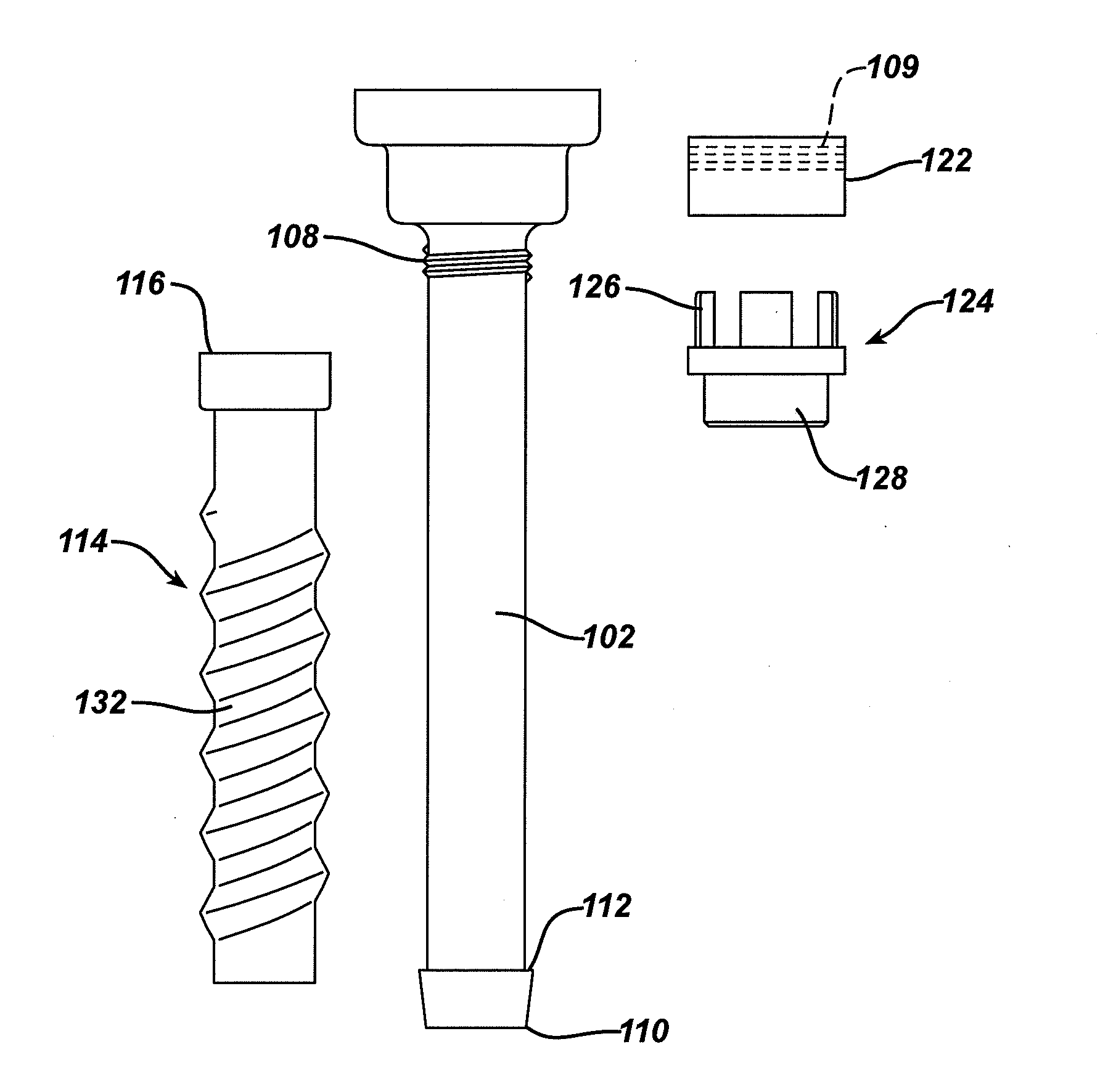
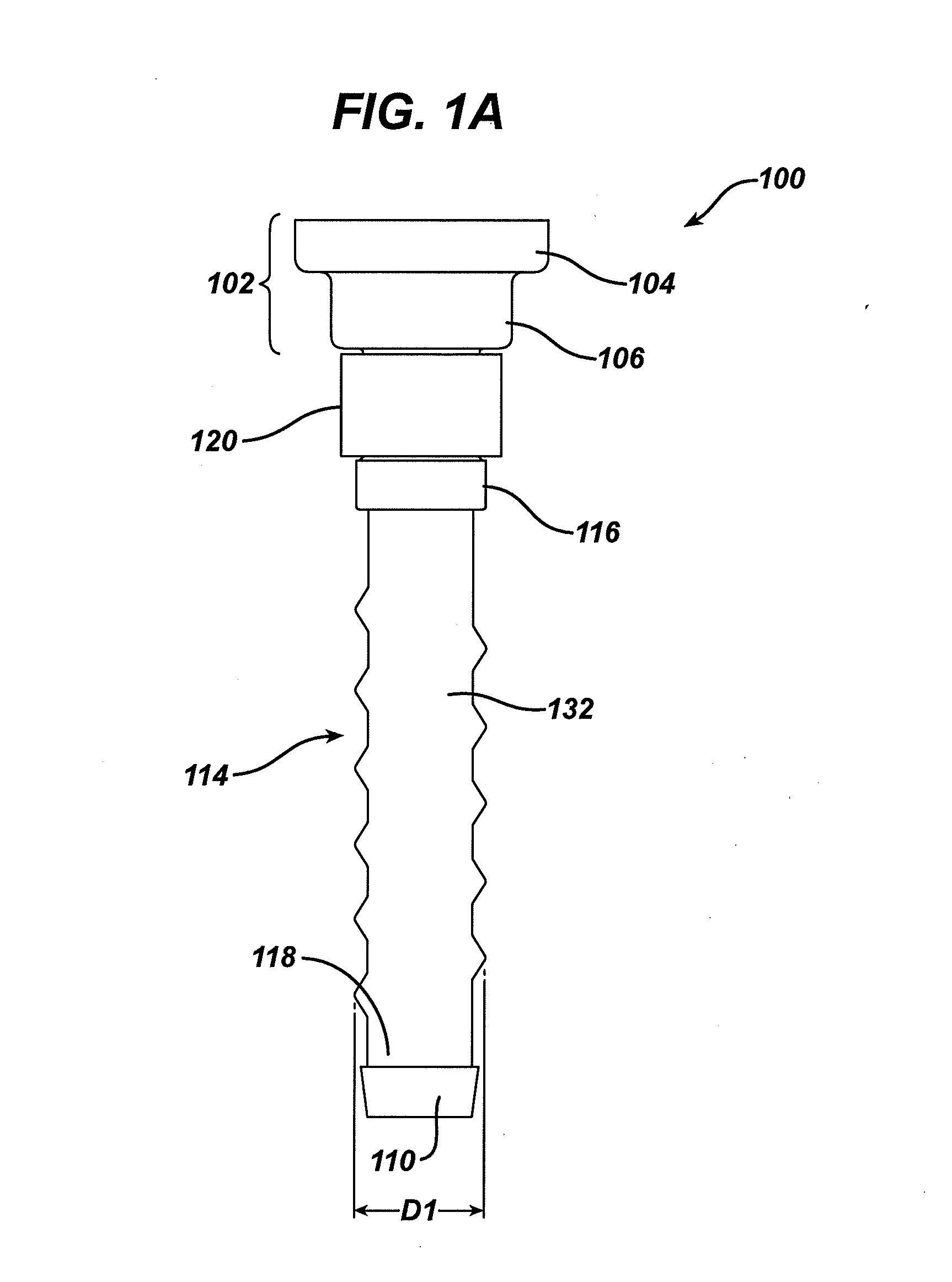
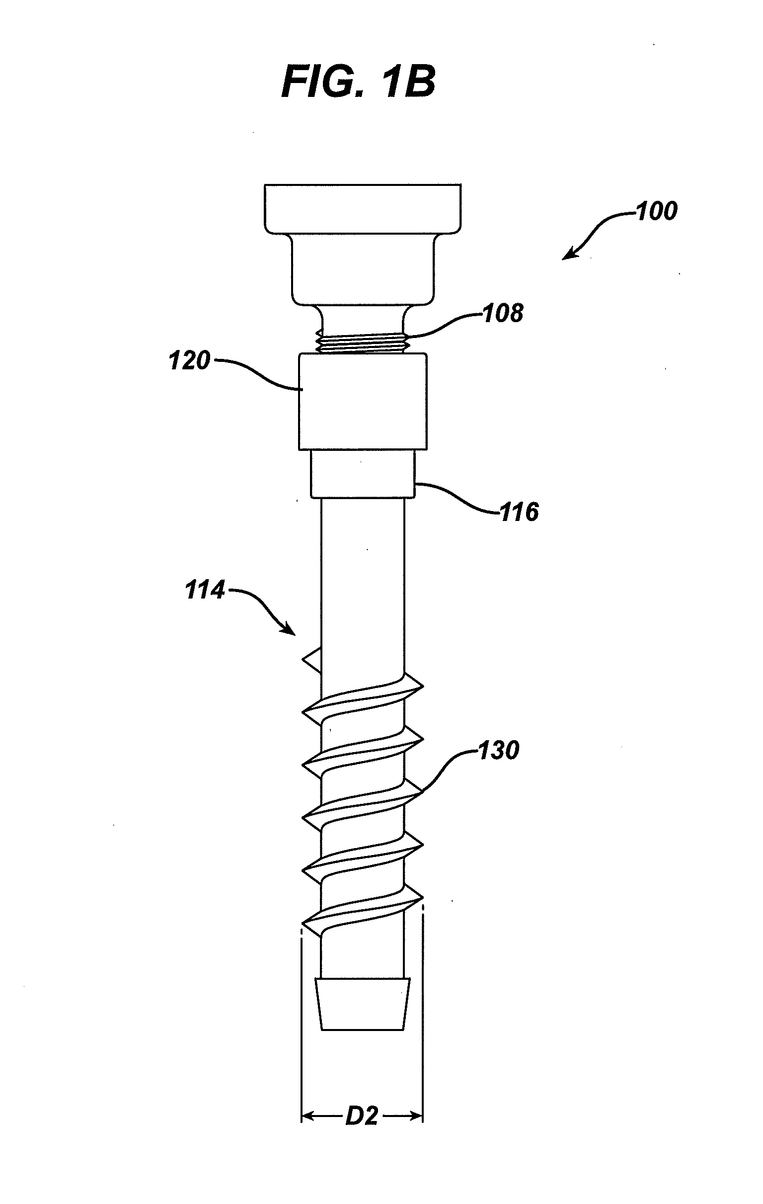
[0025]The present application provides methods and devices useful for accessing an interior surgical site using an access portal which can be inserted and removed with minimal tissue damage and whic...


PUM


Abstract

Various methods and devices are provided for accessing an interior surgical site using an access portal which can be inserted and removed with minimal tissue damage and which can form a seal with tissue while inserted. Generally, a device is provided having a rigid elongate surgical access member with a lumen extending therethrough that is configured to receive a surgical tool. The device can also include a flexible sleeve having a lumen extending therethrough that is configured to receive the elongate surgical access member. A substantially rigid collar is provided disposed adjacent to a proximal end of the flexible sleeve and having a lumen extending therethrough that is configured to receive the elongate surgical access member. In an exemplary embodiment, the collar is movable relative to the elongate surgical access member to selectively configure the flexible sleeve in a relaxed condition in which the flexible sleeve has a relatively smooth outer tissue-contacting surface and a compressed condition in which the flexible sleeve has a plurality of protrusions formed on the outer tissue-contacting surface that are configured to create a seal between the outer tissue-contacting surface and tissue.

Description

CROSS REFERENCE TO RELATED APPLICATIONS[0001]This application is a continuation application of U.S. patent application Ser. No. 12 / 030,590, entitled COMPRESSION EXPANDED CANNULA, filed Feb. 13, 2008, which is incorporated herein by reference.FIELD[0002]The present invention generally relates to methods and devices for providing access portals through which surgical instruments can be inserted. More particularly, the invention relates to devices which can be inserted into and removed from a patient with minimal tissue damage.BACKGROUND[0003]Arthroscopic, or more generally, minimally invasive surgical procedures rely on obtaining percutaneous access to an internal surgical site using small-diameter openings to gain access to the desired surgical site. In many cases, access tubes are placed through the opening to allow a variety of elongated instruments to be passed through the access tubes to gain access to an internal surgical work site without the need for large incisions. As a resu...

Claims


Application Information

Patent Timeline
Patent Type & Authority Applications(United States)
IPC IPC(8): A61B17/02
CPCA61B17/0218A61B17/3421A61B17/3439A61B2017/3419A61B2017/3484A61B2017/349A61B17/3423A61B2017/0225A61B2017/3435A61B2017/3458
Inventor WHITTAKER, GREGORY R.MCALISTER, GARYHAMILTON, JASON
Owner DEPUY MITEK INC
Why Eureka
Try Eureka