
Through-transmission welding of catheter components

a technology of transmission welding and components, applied in the direction of dilators, catheters, other domestic objects, etc., can solve the problems of loss of desirable molecular orientation, reduced catheter tracking ability through tight bends, and ultra-thin necks are especially susceptible to thermal damage, and achieve good control of hea

Inactive Publication Date: 2004-05-25
MEDTRONIC AVE
View PDF20 Cites 66 Cited by
  • Summary
  • Abstract
  • Description
  • Claims
  • Application Information

AI Technical Summary

Benefits of technology

This method provides a secure, flexible bond with minimal thermal damage to the balloon and broader material selection, ensuring mechanical strength and resistance to hydraulic leakage under high pressures, enhancing the catheter's ability to navigate tortuous passageways.

Problems solved by technology

Such ultra-thin necks are especially susceptible to thermal damage if heat welding is used to attach the balloon to the catheter.
When the balloons are bonded using adhesive between the necks and the catheter, the increased stiffness in this area can reduce the ability of the catheter to track through tight bends.
While welding improves the joint flexibility compared to the use of adhesives, it brings about new difficulties, including the sufficient control of heat to create a satisfactory bond without damaging the surrounding structure.
The most significant damage caused by poorly controlled welding heat is stiffening of the balloon cones resulting from crystallization, which is a loss of desirable molecular orientation achieved during stretch blow-molding of the balloon.
Thermal control is especially difficult in small balloon catheters such as those used in the treatment of coronary artery disease.
A disadvantage of this process is that very thin balloon necks may peel back as the assembly moves into the mold.
Thus, the designer's choice of materials is limited.
Thus, the known laser process solves some of the heat control problems in balloon welding, but requires a limited selection of particular pairs of polymers and, alternatively, the use of an extra weld element made of a material that is different from these particular polymer pairs.

Method used


Image

  • Through-transmission welding of catheter components
  • Through-transmission welding of catheter components
  • Through-transmission welding of catheter components

Examples


Embodiment Construction

The following description will be specifically provided in the context of coronary angioplasty dilatation catheters, the invention is not so limited and is applicable to other catheter assemblies and procedures. For example, it will be understood that the present invention also applies to balloon catheters used for peripheral angioplasty, drug delivery, stent delivery and the like.

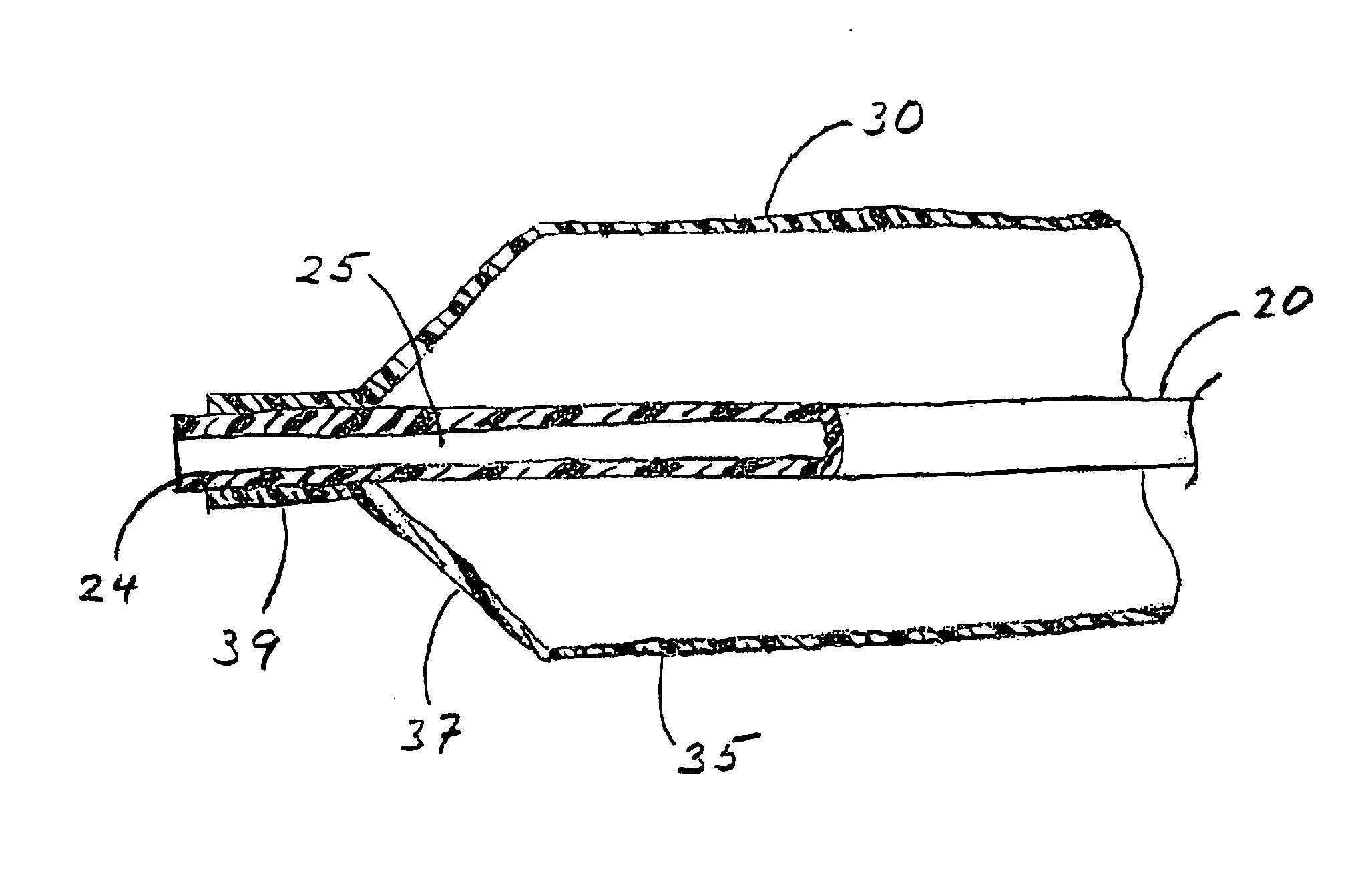
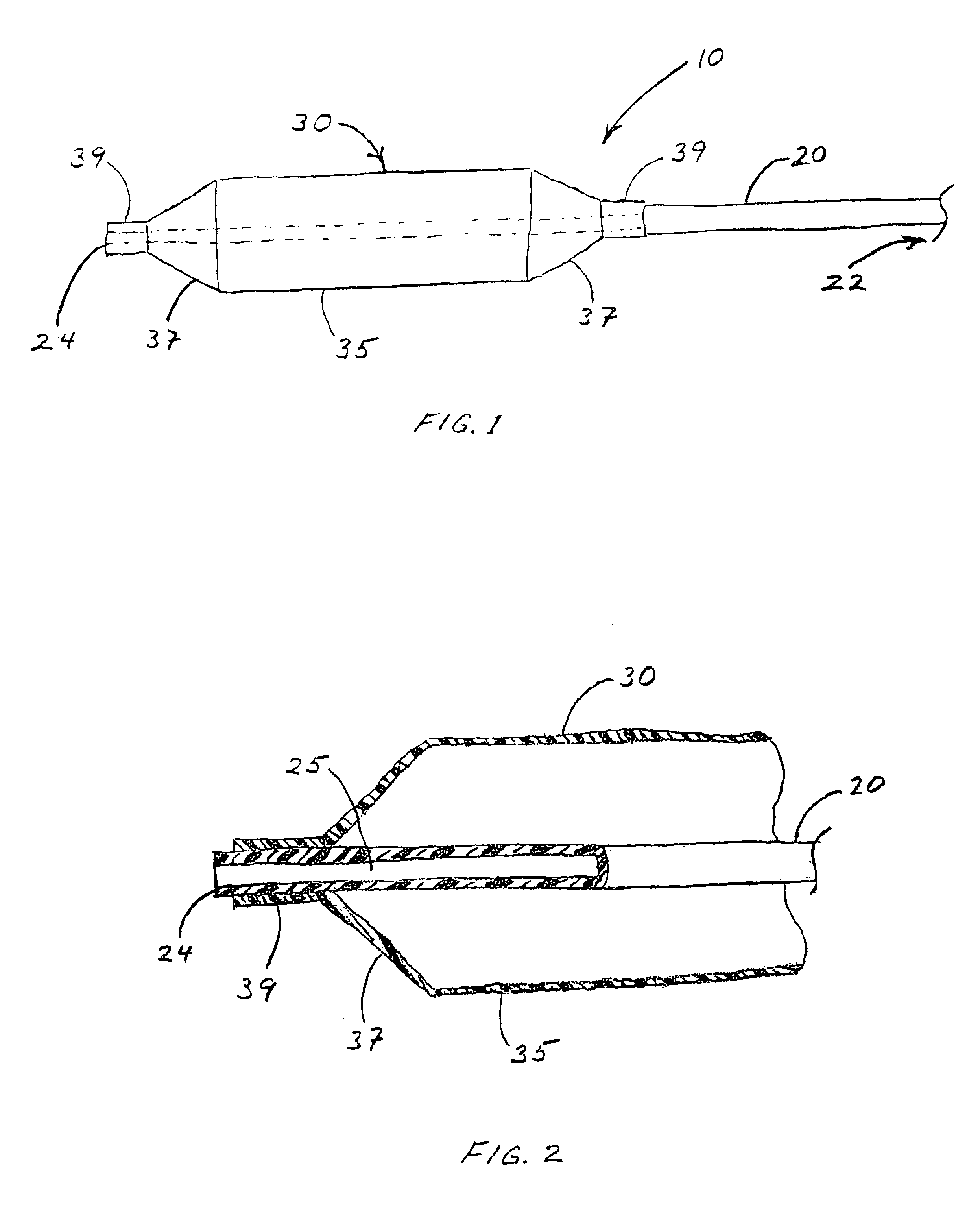
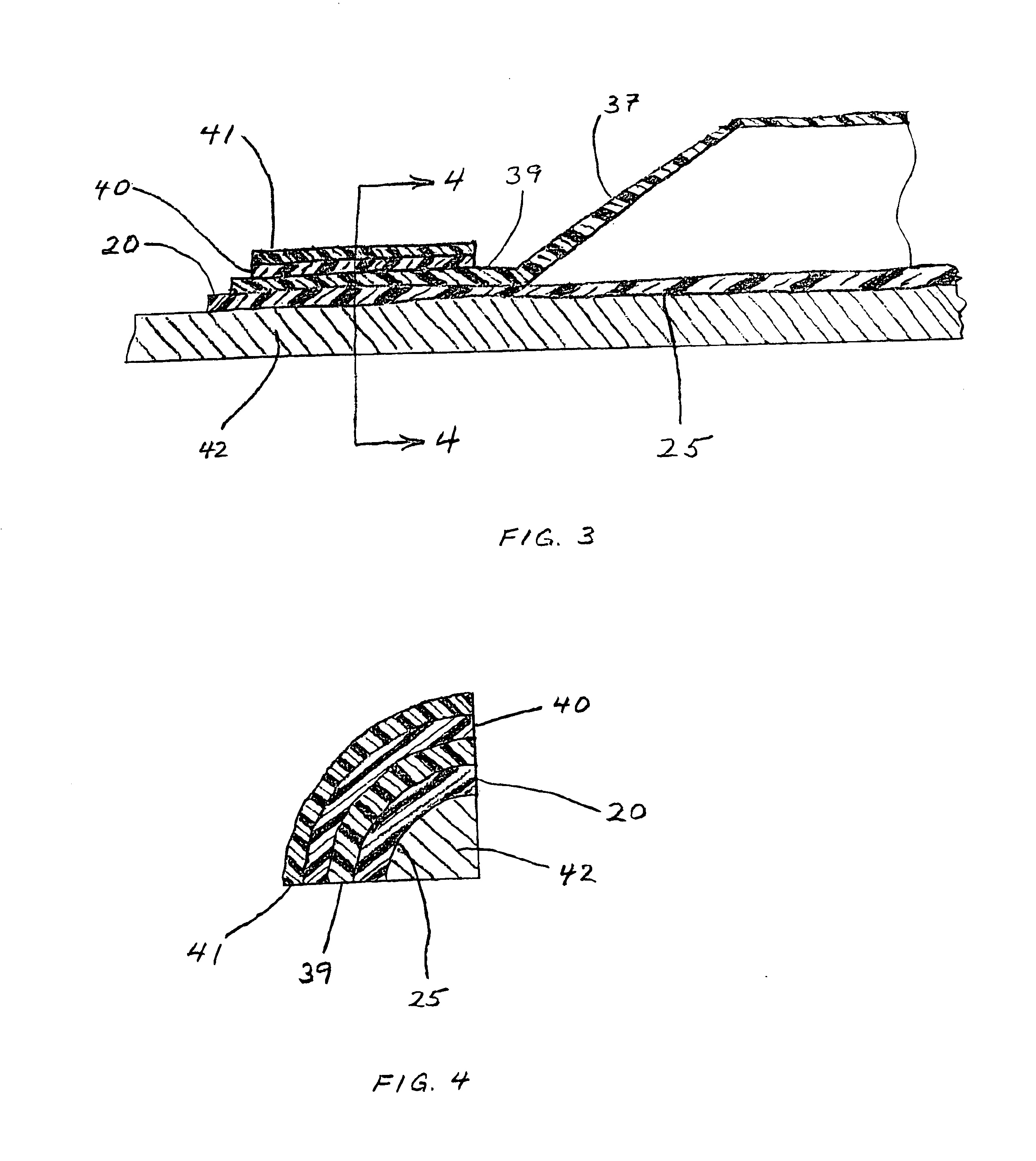
FIGS. 1 and 2 show the distal portion of balloon angioplasty catheter 10. The balloon catheter comprises an elongated, flexible catheter shaft 20 having a proximal end 22 and a distal end 24. A balloon member 30 is disposed near distal end 24 of catheter shaft 20. Balloon 30 comprises generally cylindrical dilating portion 35 having conical ends 37 tapering to shorter, smaller diameter, cylindrical necks 39 that fit closely around the distal portion of catheter shaft 20 where they are attached. Balloon 30 may be inflated and deflated through a lumen formed in the catheter shaft, which passageway is not sho...


PUM

PropertyMeasurementUnit
wavelengthaaaaaaaaaa
sizeaaaaaaaaaa

Abstract

A process for forming a heat weld between a catheter shaft and a surrounding balloon comprises selecting an elongate catheter shaft formed of thermoplastic polymeric material that is opaque to red and near-infrared light, and selecting a balloon formed of thermoplastic polymeric material that is transparent or translucent to red and near-infrared light. While a neck of the balloon is fitted in close contact around a distal portion of the catheter shaft, a laser beam of red and near-infrared light is applied through the balloon neck to impinge on the underlying opaque distal shaft, which is heated thereby. Heat from the shaft is conducted into the surrounding balloon neck so that adjacent annular portions of both components melt and mix. The molten materials are allowed to cool, forming a secure weld joint between the neck and the shaft. The process yields strong, flexible bonds between balloons and catheter shafts that may be selected from a wide variety of materials.

Description

This invention relates to welding components of catheters and more particularly to welding balloons to catheters. Bonds provided by such welding must provide mechanical strength, lateral flexibility, and resistance to hydraulic leakage under high pressures.Balloon catheters are used in the treatment of narrowings in tubular passageways of the human body, especially arterial obstructions, which are generally referred to as occlusions or stenoses. In particular, balloon catheters are used in procedures such as coronary angioplasty, peripheral angioplasty, drug delivery and stent delivery. During such procedures, a slender tubular catheter is threaded through the patient's passageways until the remote, or distal end of the catheter reaches the treatment site. Fluid injected into the external, proximal end of the catheter flows through a hollow lumen to reach and expand a balloon mounted to the distal end of the catheter. The fluid pressure used is varied as required to open the narrowi...

Claims


Application Information

Patent Timeline
Patent Type & Authority Patents(United States)
IPC IPC(8): A61M25/00B29C65/14B29C65/00B29C65/16B29C65/68B29C35/08B29C61/00B29C59/02
CPCA61M25/1034B29C65/1616B29C65/1635B29C65/68B29C66/1122B29C66/65B29C65/1654B29C66/53241B29C66/5344B29C66/63B29C66/83411B29C59/021B29C61/006B29C65/1674B29C66/83413B29C2035/0822B29K2995/0049B29C65/1687B29L2031/7543B29C66/73921B29K2995/0025B29K2995/0027B29C66/73361B29C66/73365B29C66/71B29C66/723B29C66/612B29K2077/00B29K2075/00B29K2067/00B29K2023/00B29K2021/00
Inventor CLARKE, GERRYO'CONNOR, GERARD M.SHERLOCK, RICHARDO'DRISCOLL, ALANMCNAMARA, CATHALMCDONAGH, HUBERT
Owner MEDTRONIC AVE
Learn More