Co-evaporation system comprising vapor pre-mixer

a technology of vapor pre-mixer and vapor pre-evaporation system, which is applied in the direction of vacuum evaporation coating, chemical vapor deposition coating, coating, etc., to achieve uniform composition ratio and uniform deposition

Inactive Publication Date: 2013-11-14
WANG KAI AN +4
View PDF9 Cites 263 Cited by
  • Summary
  • Abstract
  • Description
  • Claims
  • Application Information

AI Technical Summary

Benefits of technology

[0006]The present invention can overcome aforementioned deficiencies. The present application discloses flexible system and method for co-evaporation and co-deposition of multiple source materials. Vapor flows and thus ratio of the deposition materials are controlled by variable filters. The powers of the heating systems for different source materials are also controlled, which provide further control over the vapor fluxes. By using premixing vapor sources and tightly controlling vapor / mixture flows, the presently disclosed co-evaporation and co-deposition system can provide uniform deposition as well as uniform composition ratio over a large area substrate.
[0007]The vapor fluxes can be transported in an enclosed conduit to bring to close vicinity of the deposition surface on the substrate, which minimizes vapor leakage. The surfaces of the conduit are heated to prevent condensation of the vapor of the source material.
[0008]Moreover, the vapor fluxes can be directed in vertical, horizontal, and other directions according to the relative positions of the sources and the substrate, which provides flexibility the configurations and the foot prints of the deposition system.
[0009]Furthermore, the disclosed system uses replaceable parts to minimize source waste, and is thus economic to implement.
[0013]Implementations of the system may include one or more of the following. The method can further include controlling temperature of the vapor mixing chamber to optimize mixing of the first vapor and the second vapor. The method can further include controlling temperature of the vapor mixing chamber to enable intermediary material formation or chemical reaction of the first vapor and the second vapor. The method can further include controlling evaporation rates of the first source material and the second source material by a source evaporation controller, thereby controlling flow rates of the first vapor and the second vapor into the vapor mixing chamber. The method can further include filtering the first vapor by a vapor filter before transporting the first vapor into the vapor mixing chamber. The vapor filter can include a plurality of holes configured to form a uniform flow of the first vapor into the vapor mixing chamber. The method can further include filtering the mixed vapor by a mixed vapor filter before directing the mixed vapor toward the substrate. The mixed vapor filter can include a plurality of holes configured to form a uniform flow of the mixed vapor toward the substrate. The method can further include heating the conduits to prevent the first vapor and the second vapor from condensing on internal surfaces of the conduits. The mixed vapor can be directed by a vent to the substrate. The method can further include heating the vent to prevent the mixed vapor from condensing on internal surfaces of the vent.

Problems solved by technology

Furthermore, the disclosed system uses replaceable parts to minimize source waste, and is thus economic to implement.

Method used


Image

  • Co-evaporation system comprising vapor pre-mixer
  • Co-evaporation system comprising vapor pre-mixer
  • Co-evaporation system comprising vapor pre-mixer

Examples


Embodiment Construction

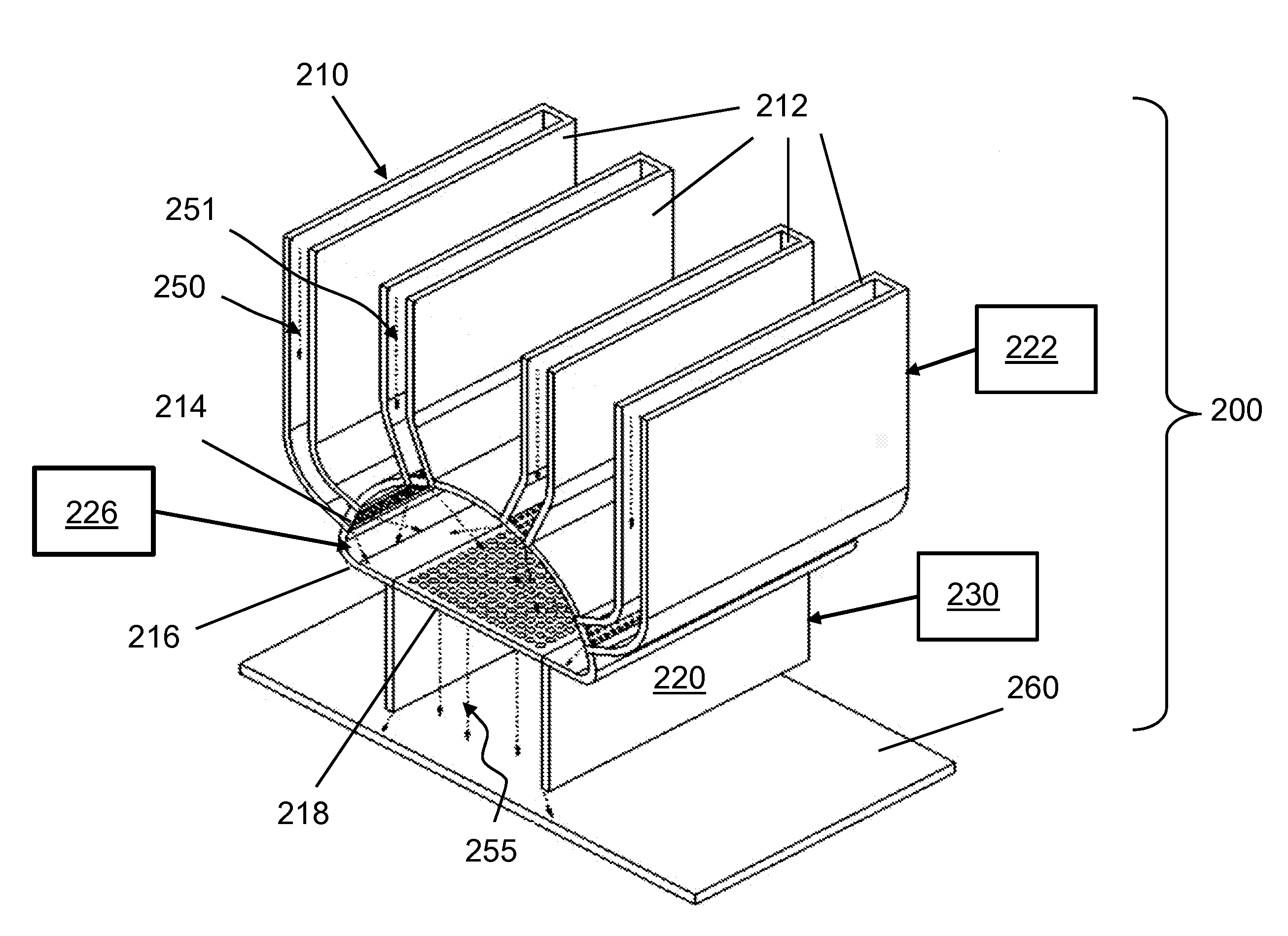
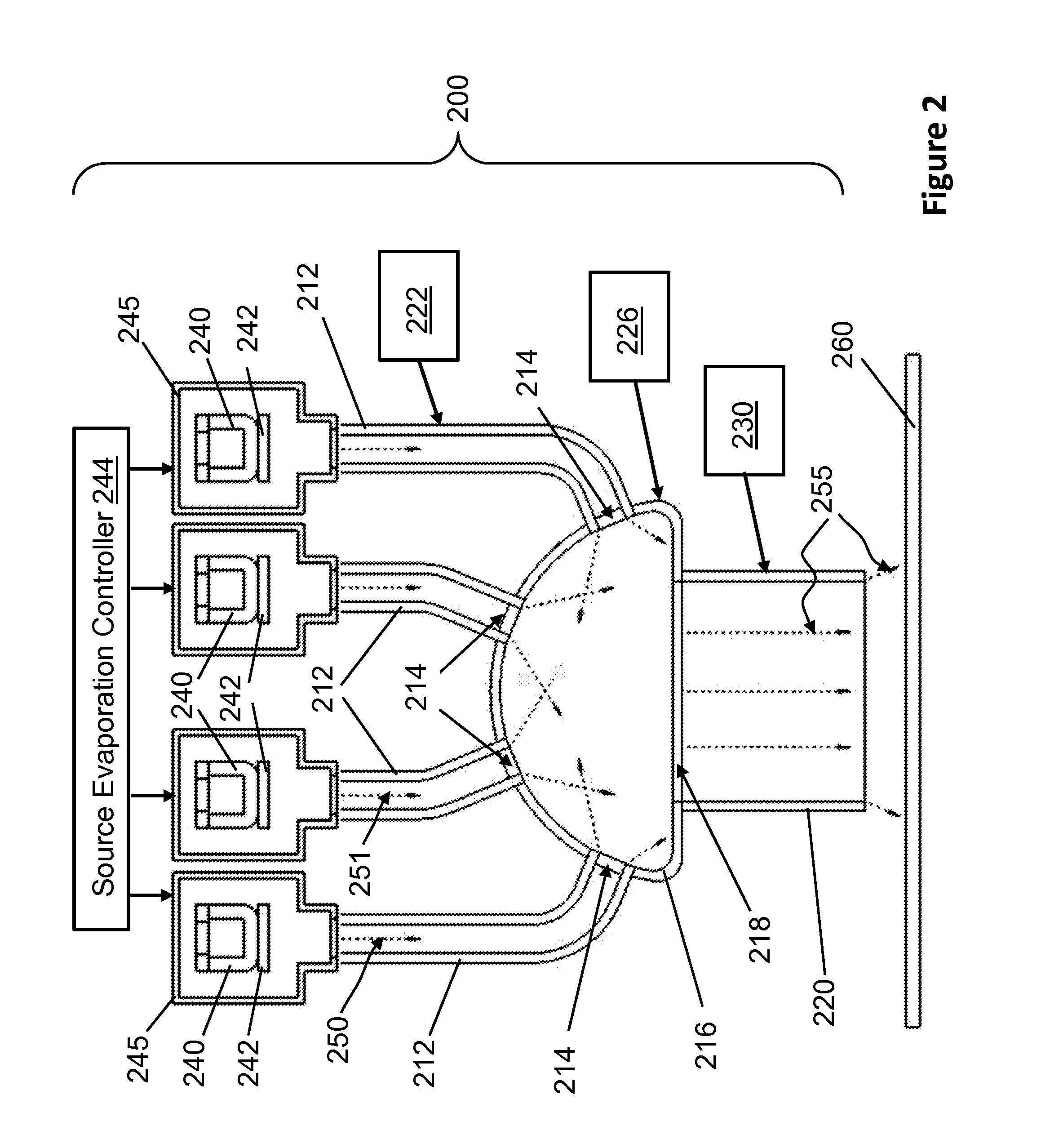
[0021]Referring to FIGS. 2-3, a processing system 200 for co-evaporation and co-deposition includes vapor channels 212 (i.e. vapor conduits) through which source vapors are introduced, vapor filters 214 at the end of the vapor channels 212, a vapor mix chamber 216 in fluidic communication with the vapor channels 212, a mixed vapor filter 218, and a vent 220 that directs fluxes of mixed vapor 255 toward a substrate 260. The processing system 200 can also include evaporation sources, chamber walls, vacuum pumping system, load-lock station, and substrate holder and transport system, which are not shown in FIGS. 2-3 and 5 for clarity reason.

[0022]The processing system 200 includes evaporation sources 240 that are enclosed in chambers 245. The chambers 245 are respectively connected to the vapor channels 212. The evaporation sources 240 each includes a separate heater 242 for heating and evaporating source materials. The heaters 242 in the different evaporation sources 240 are individual...


PUM

PropertyMeasurementUnit
temperatureaaaaaaaaaa
flow ratesaaaaaaaaaa
strengthsaaaaaaaaaa

Abstract

A processing system for depositing a plurality of source materials on a substrate, includes a first thermal evaporation source that can evaporate a first source material to produce a first vapor, a second thermal evaporation source that can evaporate a second source material to produce a second vapor, a vapor mixing chamber that allows the first vapor and the second vapor to be mixed to produce a mixed vapor, and conduits that can separately transport the first vapor and the second vapor to the vapor mixing chamber. The mixed vapor can be directed toward a substrate to deposit a mixture of the first source material and the second source material on the substrate. The processing system can also include vapor filters configured to regulate flows of the first vapor and the second vapor, and a mixed vapor filter to regulate flow of the mixed vapor.

Description

[0001]The present application claims priority to pending U.S. Provisional Patent Application 61 / 645,770, entitled “Co-evaporation System Comprising Vapor Pre-mixer”, filed by the same inventors on May 11, 2012, the disclosures of which is incorporated herein by reference.BACKGROUND OF THE INVENTION[0002]The present application relates to vacuum deposition technologies for depositing multiple materials.[0003]In a conventional co-evaporation and co-deposition system 100, shown in FIG. 1, includes thermal evaporation sources 110, 120 for depositing materials to a substrate 130. The deposition sources 110, 120 include heaters 111, 121 respectively for heating source materials 112, 122. During evaporation, the heaters 111, 121 heat and vaporize the source materials 112, 122. The vapors are mixed in the vacuum and then condense on the substrate 130 to allow the two source materials to be deposited on the substrate 130. Some vapors condense on chamber walls (not shown) or other objects bes...

Claims


Application Information

Patent Timeline
Patent Type & Authority Applications(United States)
IPC IPC(8): C23C16/455C23C16/52
CPCC23C14/243C23C14/562C23C16/45512C23C16/45565
Inventor WANG, KAI-ANWONG, MICHAELYE, MAOSHENGTING, ALBERTLIN, ENHAO
Owner WANG KAI AN
Why Eureka
Try Eureka