
Instrument and method for high-speed perfusion imaging

Inactive Publication Date: 2013-11-07
ECOLE POLYTECHNIQUE FEDERALE DE LAUSANNE (EPFL)
View PDF2 Cites 38 Cited by
  • Summary
  • Abstract
  • Description
  • Claims
  • Application Information

AI Technical Summary

Benefits of technology

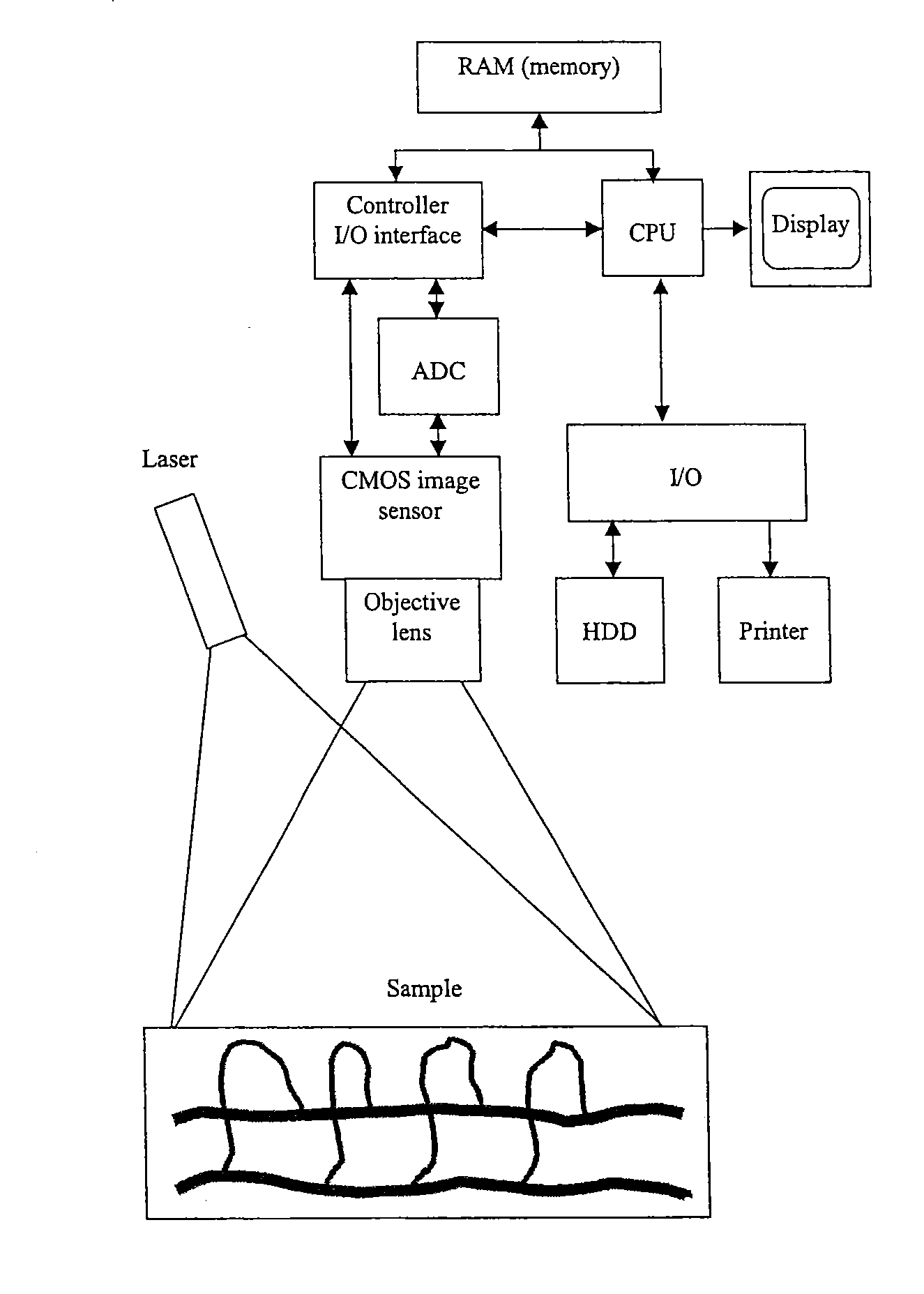
This patent describes an instrument that combines the benefits of two techniques for accurate and real-time monitoring of microcirculation in tissue. It includes a laser source, a light collector, and a 2D array of detectors that collect the laser light. The detection unit also includes a control unit, a signal processor, and a display to show the results. The instrument can provide flow-related data and images of selected areas of interest on a sample.

Problems solved by technology

However this scanning approach is time-consuming and suffers from artifacts caused by the mechanical steering of the probing laser beam.
In current commercial available LDPI systems these artifacts are circumvented on an expense of imaging time.
However, the technique can be hardly exploited for flow measurements, where either concentration or speed of moving particles is not known in advance.
The LSI is true real-time imaging technique, however as explained above the LSI signal approach cannot discriminate between concentration of flowing particles and their speed.
In LSI those signals are always intricately mixed i.e. it is impossible to deduce from speckle contrast changes in concentration or in speed of moving particles Generally, the LSI approach alone is more likely to be a qualitative indicator of blood flow but not a measuring instrument to accurately investigate physiological phenomena.
However LDI is perceived as a slower imaging modality in comparison to LSI.b) LSI is a fast imaging technique, however the results obtained with this technique have not the information content as LDI i.e. does not allow acquiring particles speed and concentration independently.

Method used


Image

  • Instrument and method for high-speed perfusion imaging
  • Instrument and method for high-speed perfusion imaging
  • Instrument and method for high-speed perfusion imaging

Examples


Embodiment Construction

[0047]An object of this invention is to propose an instrument for high-speed high-resolution imaging of microcirculation in tissues and to overcome the disadvantages of the prior described instruments or concepts.

[0048]A further object of this invention is a high-speed laser Doppler perfusion imaging system which allows digital photography, Doppler signal measurements and image speckle contrast analysis, all performed by a single detector.

[0049]An object of this invention is to acquire the signal from a plurality of illuminated spots by individual pixels, to integrate the induced photocurrent in a programmable, adapted way for increasing the signal-to-noise ratio and to process these signals for displaying finally 2D flow-related maps (perfusion, concentration, speed) with a high frame rate.

[0050]An object of this invention is to illuminate the sample i.e. biological tissue via a fiberized system in a very homogeneous way, by a fiber, GRIN-lens combination.

[0051]A further object of ...


PUM


Abstract

A high-speed laser perfusion imaging instrument including a laser source, a detector, a signal-processing unit, data memory, and a screen to display results. A section of a sample surface is illuminated with laser light; reemitted light from the irradiated surface is collected by focusing optics on a 2D array of integrating photodetectors having elements that can be accessed individually or in a pre-defined selection of pixels at high speed. This 2D array measures intensity variations at each individual pixel. Average amplitude and mean frequency of the measured signal contain information about concentration and speed of moving blood cells. For real-time imaging, exposure time is used as a parameter to measure relative perfusion changes. These data are stored and processed with the signal-processing unit to deliver 2D flow maps of the illuminated sample section, and allow a simple overlay between a conventional image and processed flow maps.

Description

CROSS-REFERENCE TO RELATED APPLICATIONS[0001]This application is a continuation-in-part application of, and claims the benefit of priority under 35 U.S.C. §120 from, U.S. application Ser. No. 11 / 912,224, filed Oct. 22, 2007, herein incorporated by reference, which is a National Stage Application of International Application No. PCT / IB06 / 00940, filed Apr. 20, 2006. This application is based upon and claims the benefit of priority from prior International Application PCT / IB2005 / 051289, filed Apr. 20, 2005.FIELD OF THE INVENTION[0002]The invention relates to imaging systems and more particularly to a perfusion and blood flow imaging system mainly applied for medical diagnosis.BACKGROUND OF THE RELATED ART[0003]Laser Doppler Imaging (LDI) is a non-contact imaging modality based on the coherence properties of light. This imaging modality mainly developed thanks to new detector technology, software and the availability of appropriate laser sources. The performance improved steadily over t...

Claims


Application Information

Patent Timeline
IPC IPC(8): A61B5/026
CPCA61B5/0261A61B5/7257A61B5/7425
Inventor LASSER, THEOANDRE, MARCFRIEDRICH, MICHAEL
Owner ECOLE POLYTECHNIQUE FEDERALE DE LAUSANNE (EPFL)
Learn More