
Battery pack

a battery pack and battery technology, applied in secondary cells, cell components, instruments, etc., can solve the problems that the conventional system including the 14.4 the 36v cordless power tool system cannot meet all user demands, and achieve the effects of improving the ease of use of power tools, reducing the amount of heat emission, and reducing the amount of power consumption

Inactive Publication Date: 2013-11-07
SAKAKIBARA KAZUYUKI
View PDF2 Cites 32 Cited by
  • Summary
  • Abstract
  • Description
  • Claims
  • Application Information

AI Technical Summary

Benefits of technology

The solution enhances power output, extends run time, reduces weight and initial costs, and improves reliability by allowing the battery pack to function as a high-voltage source, enabling continuous operation and reducing the need for additional charging infrastructure, while maintaining safety through improved electrical insulation and protection mechanisms.

Problems solved by technology

Conventional systems including 14.4V cordless power tool systems and 36V cordless power tool systems, however, cannot satisfy all of the user demands, because these systems have been specialized to have a system design that can satisfy only part of the user demands.

Method used


Image

  • Battery pack
  • Battery pack
  • Battery pack

Examples


Embodiment Construction

[0144]Several presently preferred embodiments of the invention will be described in more detail by reference to the drawings in which like numerals are used to indicate like elements throughout.

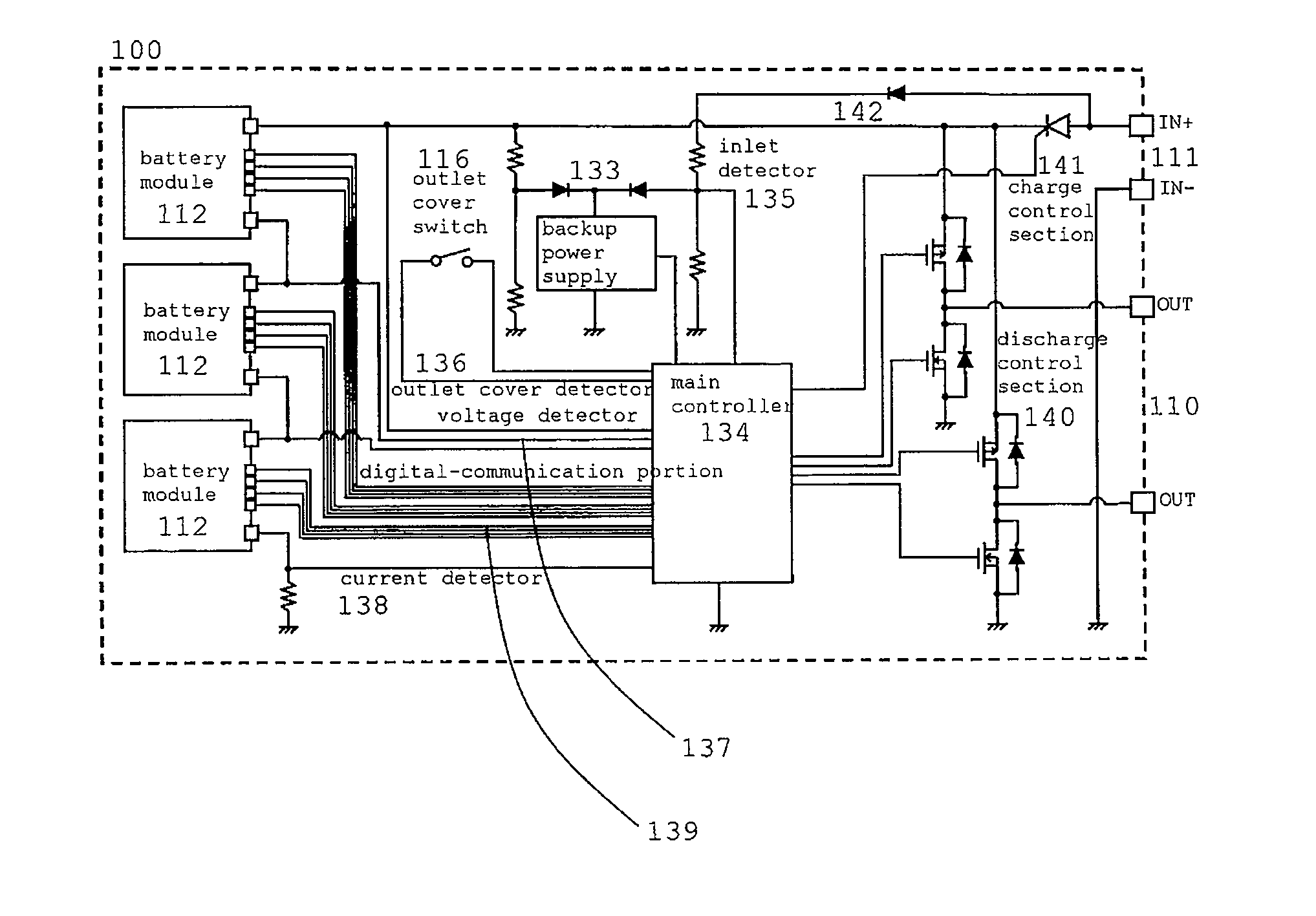
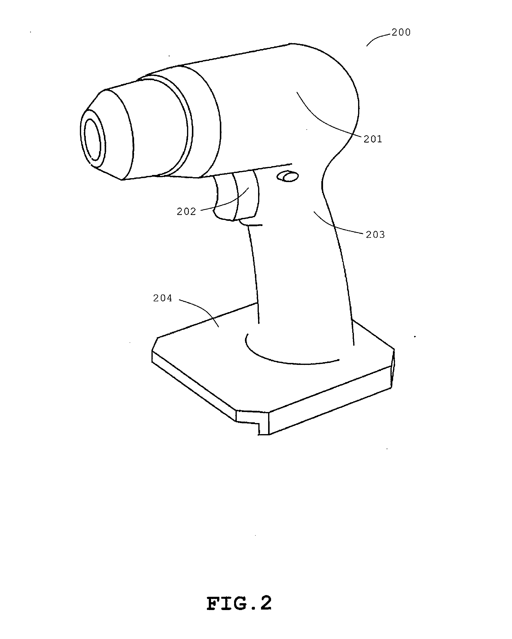
[0145]With reference to the drawings, a cordless power tool will be next described which is constructed according to an embodiment of the present invention. FIGS. 1-7 schematically illustrate the construction of a cordless power tool system, while FIGS. 8-12 schematically illustrate in block diagram how to use the cordless power tool system.

[0146]FIG. 1 illustrates the exterior of a battery pack 100 for use in the cordless power tool system. The battery pack 100 contains inner constituent components which are enclosed with an upper case 101 and a lower case 102 both of which are made of electrically-insulating material. The upper case 101 includes a movable hook-button 103; an engagement recess 104; slide rails 105; an outlet 106 for discharging which is identical in shape to the outlet of th...


PUM

PropertyMeasurementUnit
voltageaaaaaaaaaa
voltageaaaaaaaaaa
output voltageaaaaaaaaaa

Abstract

A cordless power tool system is provided which is driven by using a battery pack as a power source, and which has work performance equivalent to an AC power tool is driven by using a commercial power source as a power source. The cordless power tool system is configured to include: a battery pack in which DC voltage of battery modules is converted into AC voltage, to thereby output the AC voltage having a level which is comparable to that of the commercial power source; a cordless power tool which is driven by using the battery pack as a power source; an electrical cord adapter which allows power supply from the commercial power source to the battery pack for charging the battery pack; and an electrical cord adapter which allows power supply from the commercial power source to the cordless power tool for driving the cordless power tool.

Description

CROSS-REFERENCE TO RELATED APPLICATIONS[0001]The present application is based on Japanese Patent Application No. 2007-237583 filed Sep. 13, 2007, and International Application No. PCT / JP2008 / 066334 filed Sep. 10, 2008, the contents of which are incorporated herein by reference in their entirety.[0002]This application is a continuation application of International Application No. PCT / JP2008 / 066334 filed Sep. 10, 2008, now pending, which was published in Japanese under PCT Article 21(2).BACKGROUND OF THE INVENTION[0003]1. Field of the Invention[0004]The present invention relates to battery packs which are constructed with rechargeable batteries such as Li-ion batteries.[0005]2. Description of the Related Art[0006]Conventionally, a cordless power tool (see Japanese Patent Application Publication No. 2002-254355, for example) operates, such that a battery pack is charged via a charger with electricity which is supplied from a commercial power source, and such that a DC motor is driven u...

Claims


Application Information

Patent Timeline
Patent Type & Authority Applications(United States)
IPC IPC(8): H02J7/00B25F5/00G01R31/36H01M50/569H02J7/02
CPCH02J7/0068B25F5/00H01M10/425H01M10/441H01M10/443H01M10/482H01M10/486H02J2207/20Y02E60/10H02J7/0013H02J7/0048H02J7/005H01M50/569
Inventor SAKAKIBARA, KAZUYUKI
Owner SAKAKIBARA KAZUYUKI
Learn More