Eureka AIR delivers breakthrough ideas for toughest innovation challenges, trusted by R&D personnel around the world.

Locking system for floorboards

a locking system and floor board technology, applied in the direction of roof coverings, structural elements, building components, etc., can solve the problems of significantly more difficult taking up and function, and achieve the effect of facilitating the opening of the locking when taking up an installed floor, not easily visible, and easy angled downwards

Inactive Publication Date: 2006-02-28
VÄLINGE INNOVATION AB
View PDF354 Cites 63 Cited by
  • Summary
  • Abstract
  • Description
  • Claims
  • Application Information

AI Technical Summary

Benefits of technology

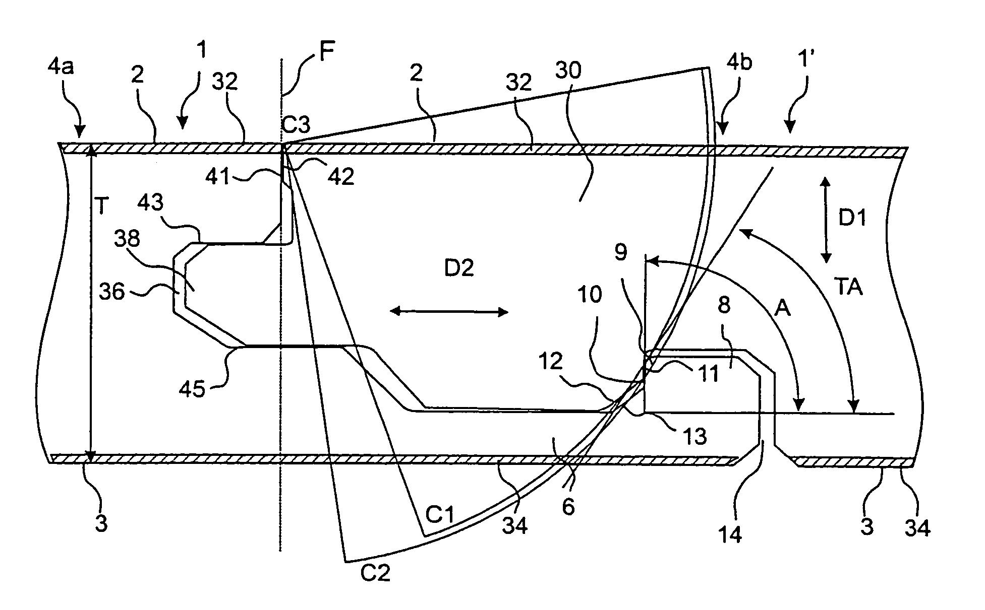
[0023]The vertical joint system, which comprises locking elements and locking grooves, has two coacting parts, viz. a locking part with operative locking surfaces which prevent the floorboards from sliding apart, and a guiding part, which positions the boards and contributes to the locking element being capable of being inserted into the locking groove. The greater the angular difference between the locking surface and the guiding part, the greater the guiding capacity.
[0029]Perpendicular locking surfaces can be made openable if interaction between a number of factors is utilised. The strip should be wide in relation to the floor thickness and it should have good resilience. The friction between the locking surfaces should be minimised, the locking surface should be small and the fibre material in the locking groove, locking element and upper joint edges of the locking system should be compressible. Moreover, it is advantageous if the boards in the locked position can assume a small play of a few hundredths of a millimeter between the operative locking surfaces of the locking groove and the locking element if the long side edge portions of the boards are pressed together.
[0031]It would be a great advantage if openable locking surfaces could be made with greater degrees of freedom and a high locking angle, preferably 90°, in combination with narrow strips which reduce waste in connection with working. The manufacture would be facilitated since working tools would only have to be guided accurately in the horizontal direction and the joint would obtain high strength.
[0038]The invention is also based on a second understanding which is related to the motions during upward angling and taking-up of an installed floor. The clearance angling, i.e. the tangent to a circular arc with its centre where the vertical joint plane intersects the upper side of the floorboard, is higher in the upper part of the locking element than in its lower part. If a part of the locking surface, which in prior-art technique is placed in the lower part of the locking element and the locking groove respectively, is placed in the upper part instead according to the invention, the difference in degree between the locking angle and the clearance angle will be smaller, and the opening of the locking when taking up an installed floor will be facilitated.

Problems solved by technology

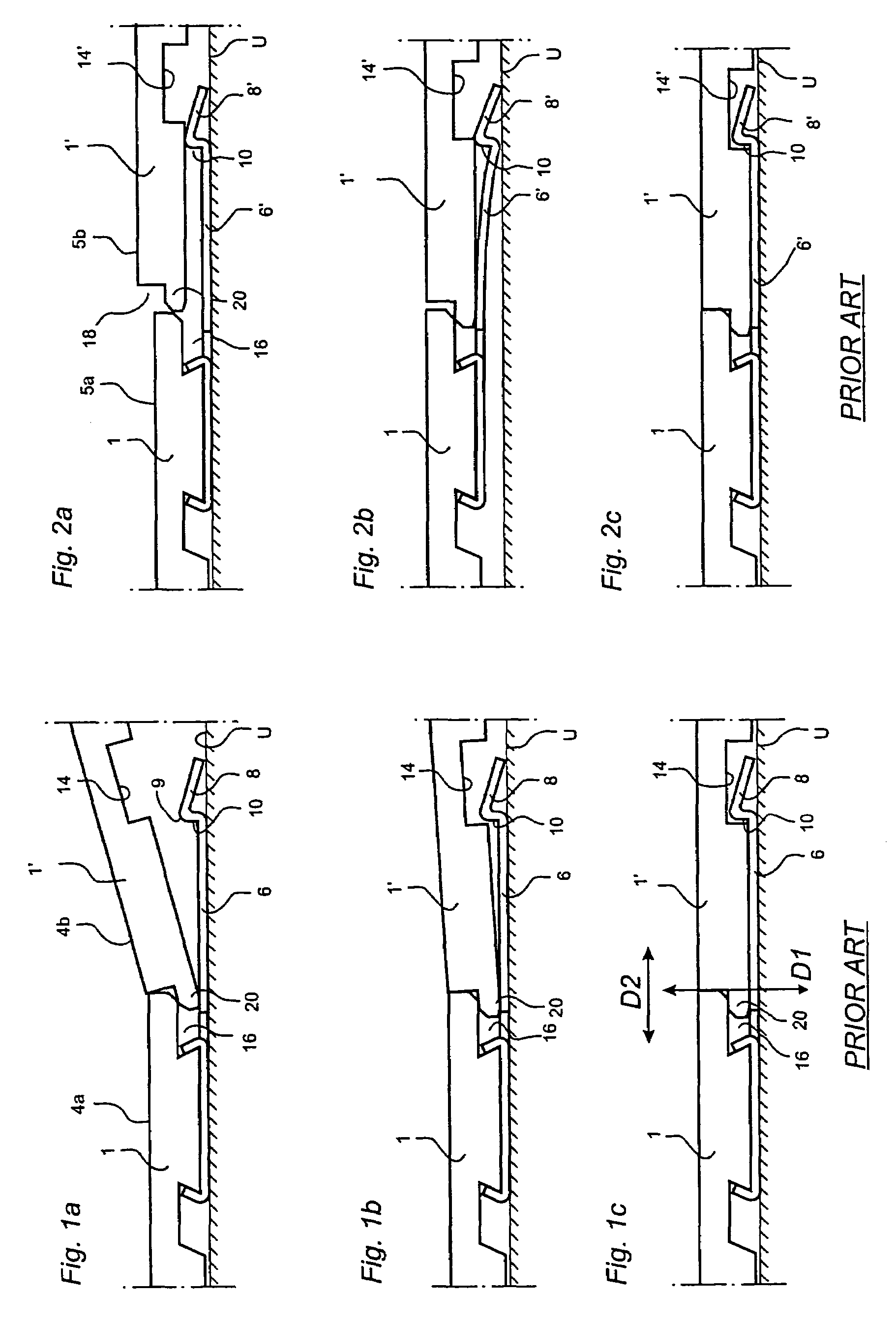
The drawback of this design of the locking element is the taking-up function, which is a vital part in most mechanical locking systems.
If the locking angle is greater than the clearance angle, the parts of the locking system will overlap each other in upward angling, which makes the taking-up considerably more difficult.

Method used


Image

  • Locking system for floorboards
  • Locking system for floorboards
  • Locking system for floorboards

Examples


Embodiment Construction

[0051]Prior to the description of preferred embodiments, with reference to FIG. 5, a detailed explanation will first be given of the most important parts in a strip lock system.

[0052]The invention can be applied in joint systems with a worked strip which is made in one piece with the core of the board, or with a strip which is integrated with the core of the board but which has been made of a separate material, for instance aluminium. Since the worked embodiment, where strip and core are made of the same material, constitutes the greatest problem owing to higher friction and poorer flexibility, the following description will focus on this field of application.

[0053]The cross-sections shown in FIG. 5 are hypothetical, not published cross-sections, but they are fairly similar to the locking system of the known floorboard “Fiboloc®” and to the locking system according to WO 9966151. Accordingly, FIG. 5 does not represent the invention but is only used a starting point of a description ...


PUM


Abstract

The invention relates to a locking system for mechanical joining of floorboards (1, 1′), a floorboard having such a locking system and a flooring made of such floorboards. The locking system has mechanical cooperating means (36, 38; 6, 8, 14) for vertical and horizontal joining of adjoining floorboards. The means for horizontal joining about a vertical plane (F) comprise a locking groove (14) and a locking strip (16) which is located at opposite joint edge portions (4a, 4b) of the floorboard (4). The locking strip (6) projects from the joint plane (F) and has an upwards projecting locking element (8) at its free end. The locking groove (14) is formed in the opposite joint edge portion (4a) of the floorboard at a distance from the joint plane (F). The locking groove (14) and the locking element (8) have operative locking surfaces (10, 11). The locking surfaces are essentially plane and spaced from the upper side of the projecting strip and inside the locking groove and make a locking angle (A) of at least 50° to the upper side of the board. Moreover the locking groove has a guiding part (12) for cooperation with a corresponding guiding part (6) on the locking element (8).

Description

TECHNICAL FIELD[0001]The invention generally relates to the field of mechanical locking of floorboards. The invention relates to an improved locking system for mechanical locking of floorboards, a floorboard provided with such an improved locking system, and a flooring made of such mechanically joined floorboards. The invention generally relates to an improvement of a locking system of the type described and shown in WO 9426999 and WO 9966151.[0002]More specifically, the invention relates to a locking system for mechanical joining of floorboards of the type having a core and preferably a surface layer on the upper side of the core and a balancing layer on the rear side of the core, said locking system comprising: (i) for horizontal joining of a first and a second joint edge portion of a first and a second floorboard respectively at a vertical joint plane, on the one hand a locking groove which is formed in the underside of said second board and extends parallel with and at a distanc...

Claims


Application Information

Patent Timeline
Patent Type & Authority Patents(United States)
IPC IPC(8): E04C3/00E04F15/02E04F15/04
CPCE04F15/02E04F15/04E04F2201/0115E04F2201/042E04F2201/0153E04F2201/023E04F2201/026E04F2201/0138
Inventor PERVAN, DARKO
Owner VÄLINGE INNOVATION AB
Why Eureka
Eureka Blog
Learn More