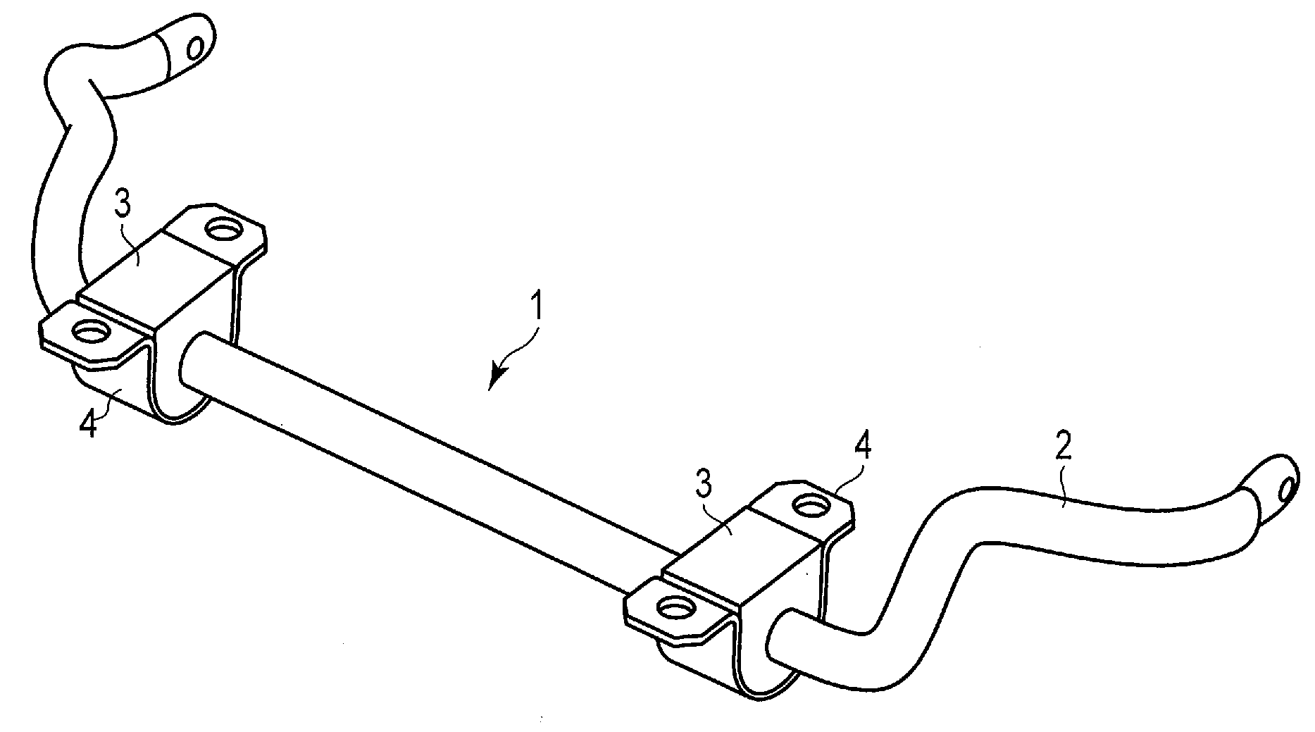
Bush- and bracket-integrated stabilizer bar
- Summary
- Abstract
- Description
- Claims
- Application Information
AI Technical Summary
Benefits of technology
Problems solved by technology
Method used
Image

Examples
example 1
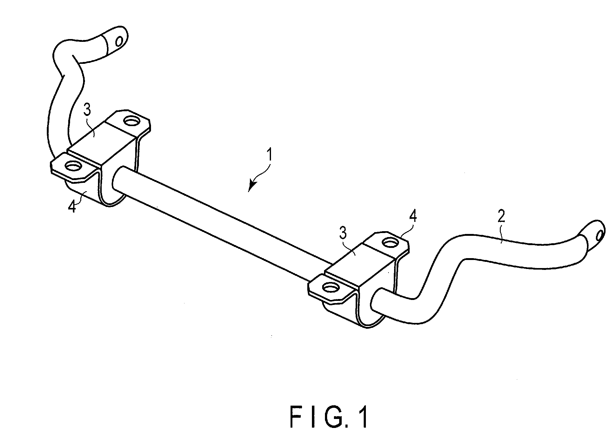
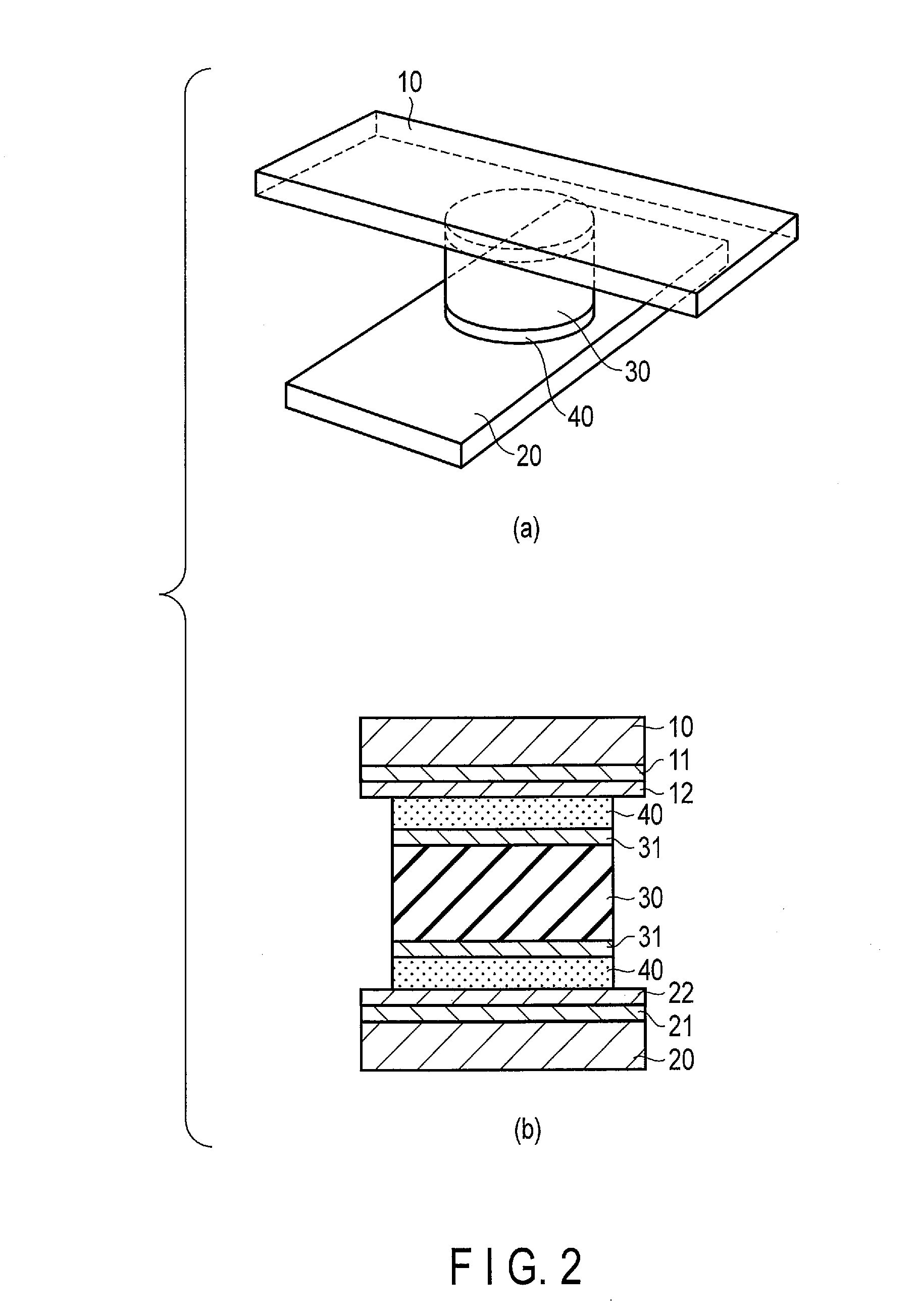
[0050]The first steel member was provided and its surface was painted with amine-based curable epoxy paint. The second steel member was provided, and its surface was painted with amine-containing cationic electrodeposition paint. Further, a disk-shaped natural rubber with Shore hardness Hs of 60 was provided. Surfaces of these members were surface-treated with a 5% trichloroisocyanuric acid solution in ethyl acetate, thereby surface treatment layers were formed. Then, these surface treatment layers were bonded with a thermosetting epoxy adhesive containing 100 parts of EPICLON EXA835 (a trade name of a product of DIC Corporation) which is a bisphenol F type epoxy resin and 20 parts of FUJICURER FXR1000 (a trade name of a product of Fujikaseikogyo Inc.) as a curing agent, thereby adhesive layers were formed. Thus, a test piece shown in FIG. 2 was produced.
[0051]As a result of performing a tensile test on the test piece, the rubber was broken. The strength was 68 MPa. As a result of a...
example 2
[0053]Disk-shaped natural rubber with Shore hardness Hs of 85 was used. A test piece was produced with other conditions being the same as those in Example 1.
[0054]As a result of performing a tensile test on the test piece, the rubber was broken, and the strength was 84 MPa. As a result of a torsion test for a trial-manufactured bush- and bracket-integrated stabilizer bar, the rubber was broken, and the strength was 172 N·m.
[0055]Further, as a result of performing a torsion test after immersion in hot water, a portion of the rubber was internally broken, and in the remaining portion, the adhesive was broken in a range wider than the case of Example 1. The breaking of the adhesive was caused by deterioration, and the adhesion strength at that time was 136 N·m.
example 3
[0056]Disk-shaped natural rubber with Shore hardness Hs of 55 was used. A test piece was produced with other conditions being the same as those in Example 1.
[0057]As a result of performing a tensile test on the test piece, the rubber was broken, and the strength was 54 MPa. As a result of a torsion test for a trial-manufactured bush- and bracket-integrated stabilizer bar, the rubber was broken, and the strength was 172 N·m.
[0058]Further, as a result of performing a torsion test after immersion in hot water, the rubber was broken in most of the adhesion region, and the adhesive was broken in a very limited region. The breaking of the adhesive was caused by deterioration, and the adhesion strength at that time was 119 N·m.
PUM
 Abstract
Description
Claims
Application Information
 - R&D
- Intellectual Property
- Life Sciences
- Materials
- Tech Scout
- Unparalleled Data Quality
- Higher Quality Content
- 60% Fewer Hallucinations
Browse by: Latest US Patents, China's latest patents, Technical Efficacy Thesaurus, Application Domain, Technology Topic, Popular Technical Reports.
© 2025 PatSnap. All rights reserved.Legal|Privacy policy|Modern Slavery Act Transparency Statement|Sitemap|About US| Contact US: help@patsnap.com