System for driving a piezoelectric load and method of making same

a piezoelectric actuator and load technology, applied in piezoelectric/electrostrictive transducers, single-ended push-pull amplifiers, generators/motors, etc., can solve the problem of low efficiency of piezoelectric actuator drivers, difficult to drive these actuators, and high cost, etc. problem, to achieve the effect of reducing the power consumption requirements and reducing the cost of the minimum power consumption

Inactive Publication Date: 2013-10-10
GENERAL ELECTRIC CO
View PDF4 Cites 10 Cited by
  • Summary
  • Abstract
  • Description
  • Claims
  • Application Information

AI Technical Summary

Benefits of technology

[0005]In accordance with one aspect of the invention, a driver system comprises a direct current (DC) voltage source and a first bi-directional DC-to-DC converter having a primary side coupled to the DC voltage source and a secondary side and comprising a control input configured to receive a first control signal configured to control conversion of a first voltage on the primary side of the first bi-directional DC-to-DC converter to a second voltage on the secondary side of the first bi-directional DC-to-DC converter. The driver system also comprises a second bi-directional DC-to-DC converter having a primary side coupled to the DC voltage source and a secondary side coupled to the secondary side of the first bi-directional DC-to-DC converter and comprising a control input configured to receive a second control signal configured to control conversion of the first voltage on the primary side of the second bi-directional DC-to-DC converter to a third voltage on the secondary side of the second bi-directional DC-to-DC converter. The first and second bi-directional DC-to-DC converters are capable of boosting the first voltage, and the second control signal is a complement of the first control signal. A voltage difference between the second and third voltages comprises an output voltage, and the output voltage comprises an amplification of the first control signal.
[0006]In accordance with another aspect of the invention, a method of manufacturing a piezoelectric driver comprises coupling a direct current (DC) voltage source to a low-voltage side of a first voltage converter and to a low-voltage side of a second voltage converter, wherein the first and second voltage converters comprise bi-directional DC-to-DC voltage converters capable of boosting a voltage from the DC voltage source. The method also comprises coupling a first high-voltage side terminal on a high-voltage side of the first voltage converter to a first side of a piezoelectric actuator, coupling a first high-voltage side terminal on a high-voltage side of the second voltage converter to a second side of the piezoelectric actuator, and coupling a second high-voltage side terminal of the first voltage converter to a second high-voltage side terminal of the second voltage converter. The method also comprises coupling a control system to the first and second voltage converters and configuring the control system to supply a first control signal to the first voltage converter and to supply a second control signal to the second voltage converter. The first control signal is configured to control the first voltage converter to convert the voltage from the DC voltage source on the low-voltage side of the first voltage converter to a first output voltage on the high-voltage side of the first voltage converter, and the second control signal is a complement of the first control signal and is configured to control the second voltage converter to convert the voltage from the DC voltage source on the low-voltage side of the second voltage converter to a second output voltage on the high-voltage side of the second voltage converter. A voltage difference between the first and second output voltages comprises a difference voltage that comprises an amplification of the first control signal.
[0007]In accordance with yet another aspect of the invention, a piezoelectric driver comprises a first bi-directional DC-to-DC voltage converter having a low-voltage side and a high-voltage side and comprises a second bi-directional DC-to-DC voltage converter having a low-voltage side and a high-voltage side. The first bi-directional DC-to-DC voltage converter comprises a first high-voltage side terminal, a second high-voltage side terminal, and wherein the first bi-directional DC-to-DC converter is capable of boosting a voltage on the first high-voltage side terminal thereof. The second bi-directional DC-to-DC voltage converter comprises a first high-voltage side terminal, a second high-voltage side terminal coupled to the second high-voltage side terminal of the first voltage converter, and wherein the second bi-directional DC-to-DC converter is capable of boosting a voltage on the first high-voltage side terminal thereof. The piezoelectric driver also comprises a direct current (DC) voltage source coupled to the low-voltage sides of the first and second bi-directional DC-to-DC voltage converters, a piezoelectric actuator coupled to the first high-voltage side terminal of the first bi-directional DC-to-DC voltage converter and coupled to the first high-voltage side terminal of the second bi-directional DC-to-DC voltage converter, and a control system coupled to the first and second voltage converters. The control system is configured to supply a first control signal to the first bi-directional DC-to-DC voltage converter, wherein the first control signal is configured to control the first bi-directional DC-to-DC voltage converter to convert a voltage on the low-voltage side of the first bi-directional DC-to-DC voltage converter to a first output voltage on the high-voltage side of the first bi-directional DC-to-DC voltage converter. The control system is also configured to supply a second control signal to the second bi-directional DC-to-DC voltage converter, wherein the second control signal is a complement of the first control signal and is configured to control the second bi-directional DC-to-DC voltage converter to convert a voltage on the low-voltage side of the second bi-directional DC-to-DC voltage converter to a second output voltage on the high-voltage side of the second bi-directional DC-to-DC voltage converter. A voltage difference between the first and second output voltages comprises a difference voltage that comprises an amplification of the first control signal.

Problems solved by technology

In applications where piezoelectric actuators are interfaced with low voltage circuitry such as in portable, consumer, aviation, or transportation electronic devices, it can be difficult to drive these actuators.
For example, when trying to drive a piezoelectric actuator with an AC voltage waveform or one with variable value with peak voltages higher than are available from a power source, known methods often accomplish this goal using complex, inefficient, large, and / or expensive drivers.
In addition, many applications where piezoelectric actuators are used call for using minimum power consumption, and inefficient piezoelectric actuator drivers having low efficiencies often fail such minimum power consumption requirements.

Method used


Image

  • System for driving a piezoelectric load and method of making same
  • System for driving a piezoelectric load and method of making same
  • System for driving a piezoelectric load and method of making same

Examples


Embodiment Construction

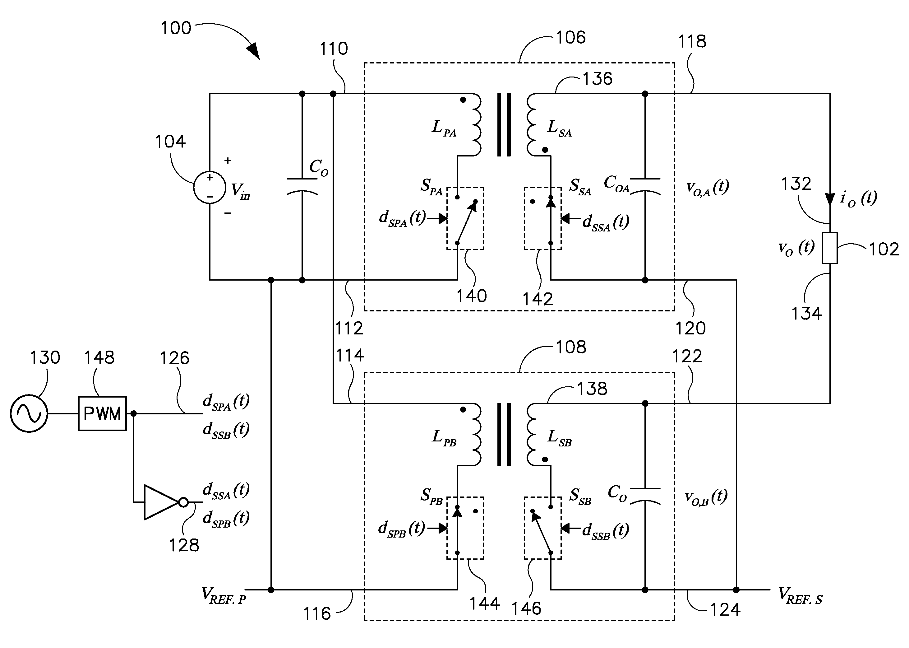
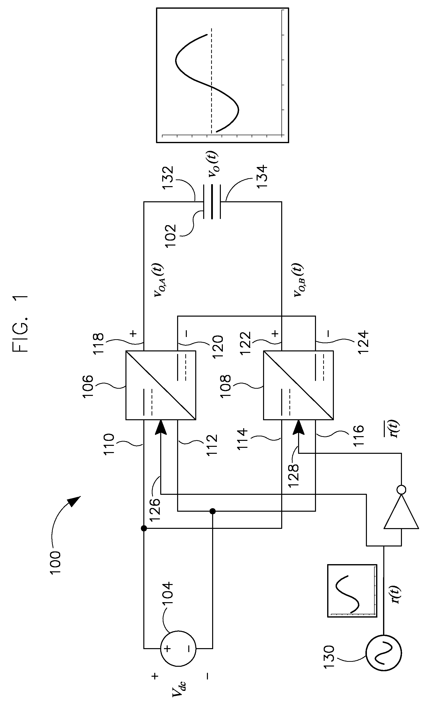
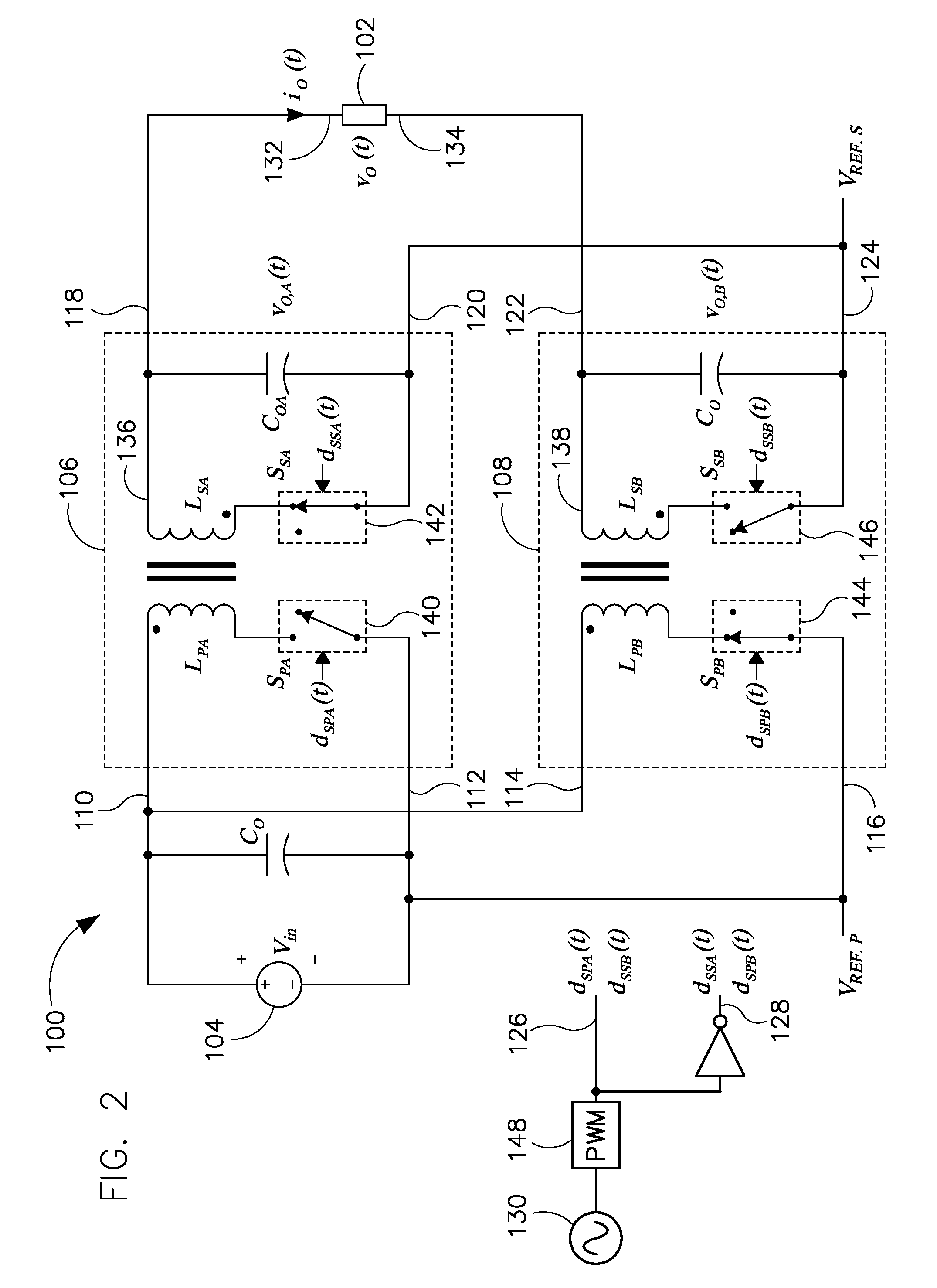
[0016]Referring to FIG. 1, a block schematic diagram illustrates a piezoelectric driver 100 coupled to a piezoelectric load or actuator 102. Piezoelectric load 102 is a capacitive or reactive load.

[0017]Piezoelectric driver 100 includes a voltage source 104 and first and second converters 106, 108. First and second converters 106, 108 are DC-TO-DC bi-directional converters / amplifiers configured to take a voltage from voltage source 104 supplied to respective pairs of low-side converter terminals 110, 112 and 114, 116 and to boost the supplied voltage to respective pairs of high-side converter terminals 118, 120 and 122, 124. First and second converters 106, 108 also buck voltages from respective terminals 118, 120 and 122, 124 to respective terminals 110, 112 and 114, 116. First converter 106 is configured to convert the voltage, vdc, from voltage source 104 to an output voltage, vOA, and second converter 108 is configured to convert the voltage, vdc, from voltage source 104 to an o...


PUM

PropertyMeasurementUnit
voltageaaaaaaaaaa
voltagesaaaaaaaaaa
output voltageaaaaaaaaaa

Abstract

A driver system comprises a direct current (DC) voltage source and a first bi-directional DC-to-DC converter having a primary side coupled to the DC voltage source and a secondary side and configured to convert a first voltage on the primary side to a second voltage on the secondary. The driver system also comprises a second bi-directional DC-to-DC converter having a primary side coupled to the DC voltage source and a secondary side coupled to the secondary side of the first bi-directional DC-to-DC converter and configured to convert the first voltage on the primary side to a third voltage on the secondary. The first and second bi-directional DC-to-DC converters are capable of boosting the first voltage, and the second control signal is a complement of the first control signal. A voltage difference between the second and third voltages comprises an output voltage that comprises an amplification of the first control signal.

Description

BACKGROUND OF THE INVENTION[0001]Embodiments of the invention relate generally to piezoelectric actuators and, more particularly, to a driver circuit for piezoelectric actuators.[0002]Piezoelectric materials are known to change dimensions upon application of an electric field. This phenomenon allows the use of piezoelectric materials to be used as actuators in micro-electro-mechanical system (MEMS) devices. For example, such actuators have been used in synthetic jet actuators that generate a synthetic jet of fluid to influence the flow of that fluid over a surface. A typical synthetic jet actuator comprises a housing defining an internal chamber. An orifice is present in a wall of the housing. The actuator further includes a mechanism in or about the housing for periodically changing the volume within the internal chamber so that a series of fluid vortices are generated and projected in an external environment out from the orifice of the housing. Examples of volume changing mechanis...

Claims


Application Information

Patent Timeline
Patent Type & Authority Applications(United States)
IPC IPC(8): H01L41/09H01L41/22H03F3/30
CPCH01L41/042H02M3/33584H01L41/107H02N2/0075Y10T29/42H02M2001/0077H02M1/0077H10N30/802H02N2/06H02M3/155H10N30/40
Inventor GLASER, JOHN STANLEYRAMABHADRAN, RAMANUJAM
Owner GENERAL ELECTRIC CO
Why Eureka
Try Eureka