Flash memory lifetime evaluation method

Inactive Publication Date: 2013-10-03
FLUIDITECH IP
View PDF57 Cites 11 Cited by
  • Summary
  • Abstract
  • Description
  • Claims
  • Application Information

AI Technical Summary

Benefits of technology

The present invention provides a method for accurately evaluating the longevity of a flash memory in an electronic device. This method can determine the ideal lifetime of the flash memory and predict its actual lifetime by retrieving parameters stored in a memory block, a memory page, and a spare area. This can help to improve the reliability and durability of the flash memory in electronic devices.

Problems solved by technology

Although the flash memory has the advantages of low cost, low power consumption and low read delay, yet the structure and operation method of the flash memory cause a risk on the use of the flash memory having a limited number of times of reading and writing data.

Method used


Image

  • Flash memory lifetime evaluation method
  • Flash memory lifetime evaluation method
  • Flash memory lifetime evaluation method

Examples


Embodiment Construction

[0014]The objects, characteristics and effects of the present invention will become apparent with the detailed description of the preferred embodiments and the illustration of related drawings as follows.

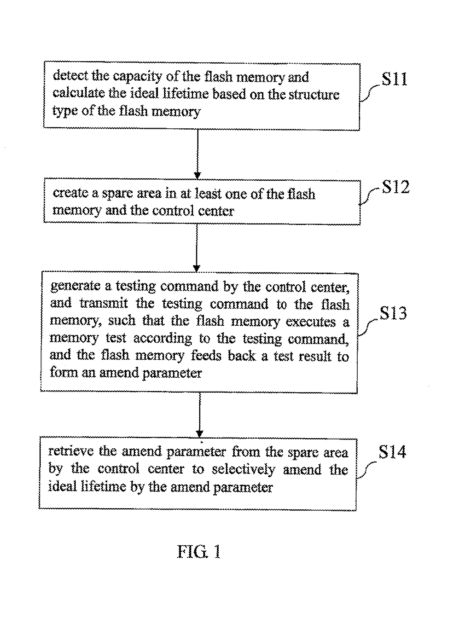
[0015]With reference to FIG. 1 for a flow chart of a flash memory lifetime evaluation method in accordance with a preferred embodiment of the present invention, the flash memory lifetime evaluation method is provided for a control center to dynamically amend, detect and evaluate an ideal lifetime of a built-in or expanded flash memory of an electronic device. Wherein, the control center refers to a driver for driving the flash memory or a remote monitoring server connected to the electronic device via the Internet for controlling the flash memory.

[0016]The flash memory lifetime evaluation method comprises the following steps:

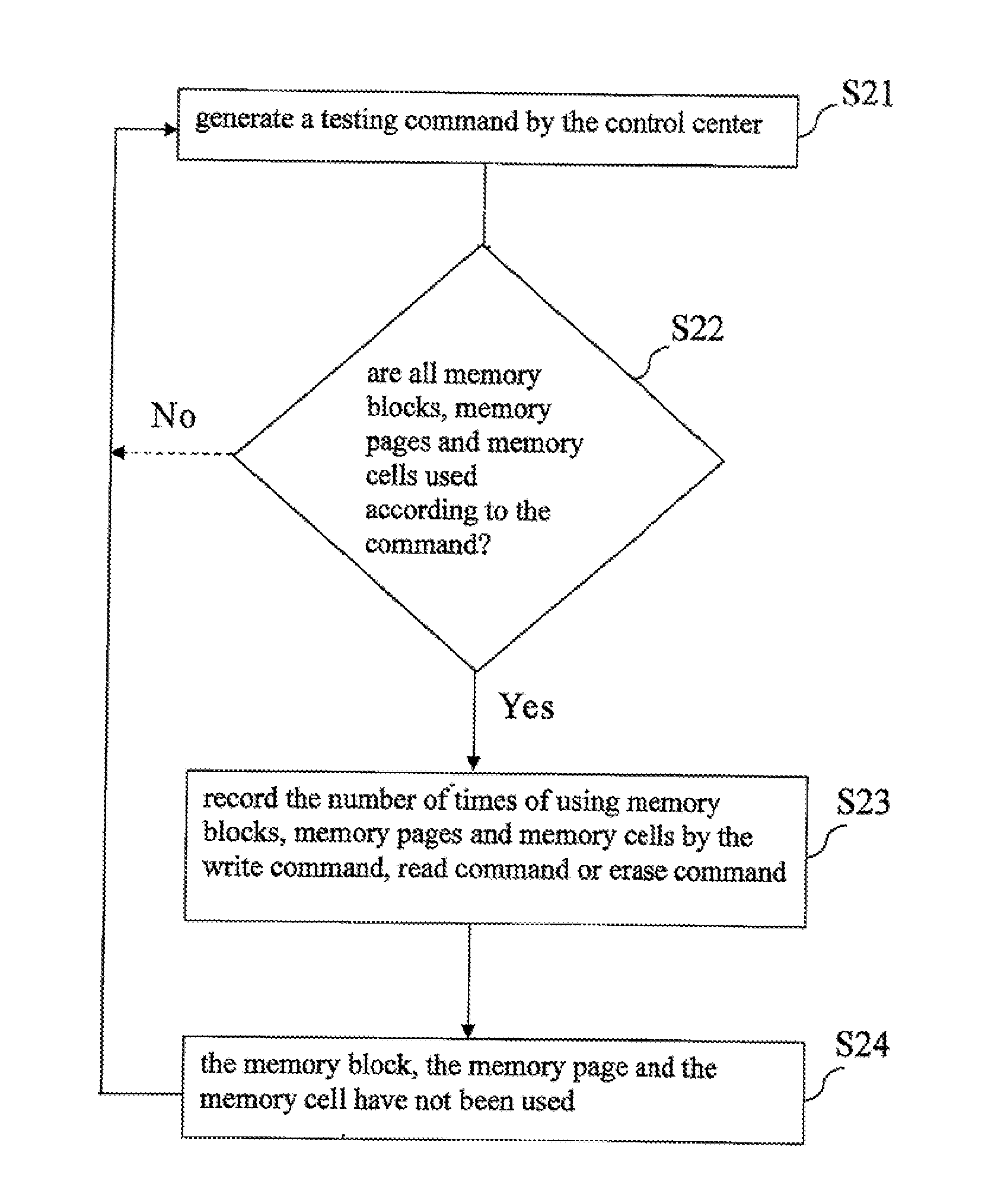
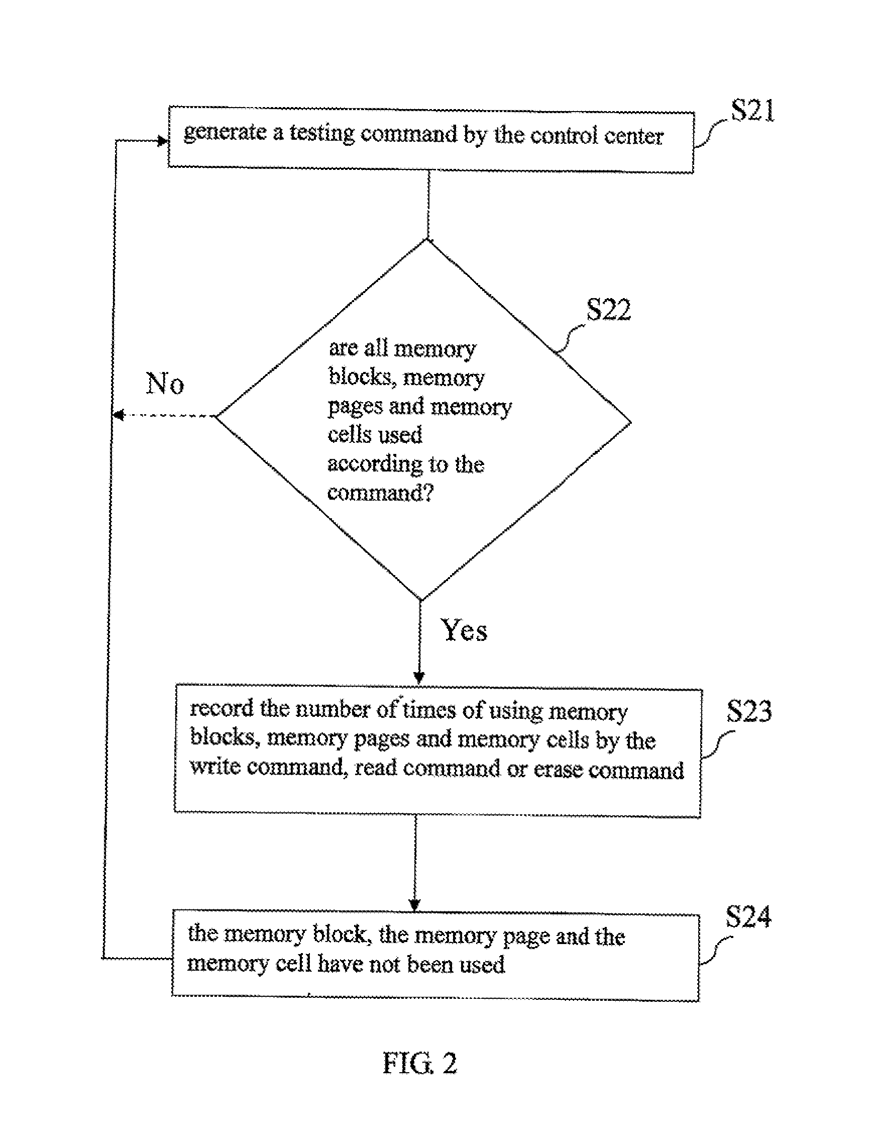
[0017]S11: Detect the capacity of the flash memory having a memory block, a memory page and a memory cell, and calculate the ideal lifetime based on the structu...


PUM


Abstract

A flash memory lifetime evaluation method is introduced for dynamically amending, detecting and evaluating an ideal lifetime (or standard lifetime) of a built-in or expanded flash memory of an electronic device, and the method comprises the steps of calculating the ideal lifetime according to the capacity of the flash memory, creating a spare area in at least one of the flash memory and the control center, generating a testing command by the control center and transmitting the testing command to the flash memory such that the flash memory executes a memory test according to the testing command, and the flash memory feeds back a test result to the spare area as an amend parameter according to the memory test, and the control center retrieves the amend parameter stored in the spare area to selectively amend the ideal lifetime by the amend parameter.

Description

FIELD OF THE INVENTION[0001]The present invention relates to a flash memory lifetime evaluation method, in particular to the method provided for a control center to dynamically amend, detect and evaluate an ideal lifetime of a flash memory in an electronic device.BACKGROUND OF THE INVENTION[0002]At present, NAND flash memory is used extensively in various electronic products such as a tablet PC, a Smartphone, a desktop computer, and a notebook computer, and the flash memory in the electronic products also serves as a storage area for storing system boot codes such as an embedded multi media card (eMMC) or an integrated solid state drive (iSSD), in addition to its a role of storing data.[0003]The flash memory uses the structure of a floating gate to latch electric charges to achieve the effect of storing data. In general, the flash memory can execute related commands including Erase, Write, and Read according to a command given by a control chip, and the flash memory uses a high-volt...

Claims


Application Information

Patent Timeline
IPC IPC(8): G11C29/10G06F11/263
CPCG11C16/3495
Inventor CHU, YUNG-CHIANG
Owner FLUIDITECH IP
Why Eureka
Try Eureka