
Method for controlling a wind turbine by optimizing its production while minimizing the mechanical impact on the transmission

a technology of mechanical impact and wind turbine, which is applied in the direction of machine/engine, process and machine control, instruments, etc., can solve the problems of not being able to take into account mechanical impact, limited performance level of linear controllers, and inability to design wind turbines which maximize efficiency, so as to minimize mechanical impact, minimize mechanical impact, and optimize the electrical energy production of wind turbines

Active Publication Date: 2013-10-03
INST FR DU PETROLE
View PDF9 Cites 6 Cited by
  • Summary
  • Abstract
  • Description
  • Claims
  • Application Information

AI Technical Summary

Benefits of technology

This patent is about a way to make wind turbines produce more electrical energy by controlling the position of the blades to account for the movement of the system and reducing the impact on the transmission. The method involves determining the optimal air pressure and electric machine torque to maximize the amount of power captured from the wind. This results in more efficient energy production.

Problems solved by technology

It is in fact pointless to design wind turbines which maximize their efficiency at even higher wind speeds, since such speeds are infrequent.
However, the performance levels of these linear controllers are limited by the greatly non-linear characteristics of the wind turbine.
However, none of these controllers makes it possible to take account for the mechanical impact (fatigue and extreme moment) on the transmission.
Most wind turbine failures are due to breakages or damage affecting the transmission.

Method used


Image

  • Method for controlling a wind turbine by optimizing its production while minimizing the mechanical impact on the transmission
  • Method for controlling a wind turbine by optimizing its production while minimizing the mechanical impact on the transmission
  • Method for controlling a wind turbine by optimizing its production while minimizing the mechanical impact on the transmission

Examples


Embodiment Construction

[0030]In the description, the following notations are used:

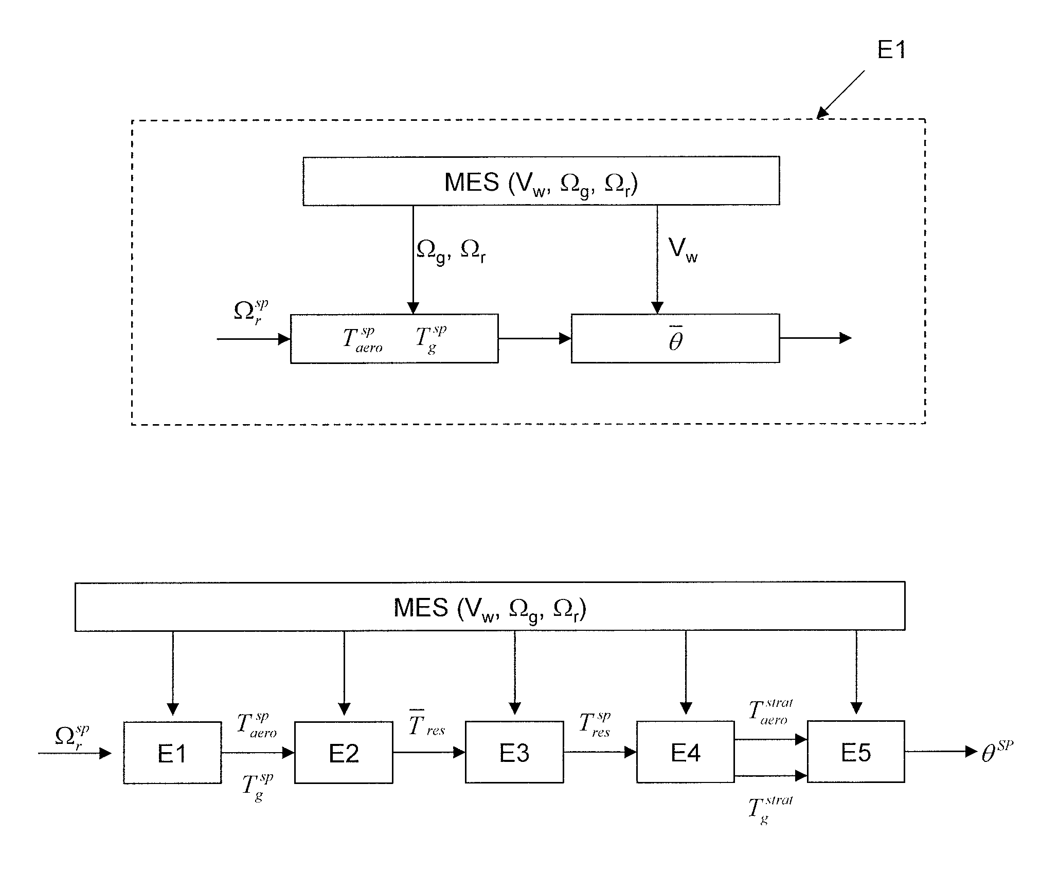
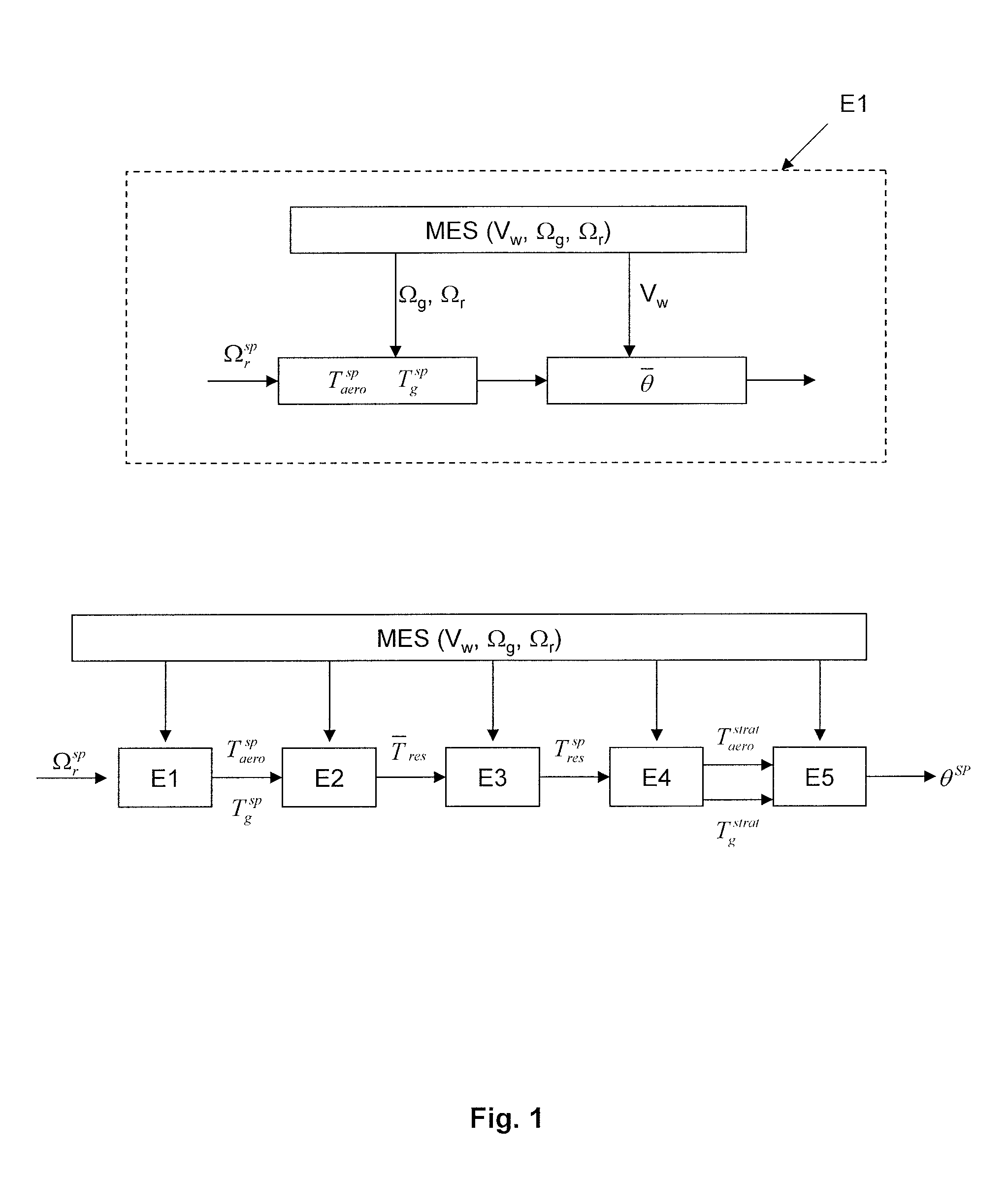
[0031]Controlled variables:[0032]θ is the pitch angle of the blades in degrees, which is also called “pitch” and which corresponds to the angle of attack to the wind of each of the blades.[0033]Tg is the torque of the electric machine in Nm; and[0034]Taero is the aerodynamic torque (rotational force applied to the rotor under the effect of the wind).

[0035]Measured variables, denoted MEAS(-):[0036]VW is the speed of the wind in m / s which is derived from a measurement from an anemometer or derived from an estimation;[0037]Ωr is the speed of the rotor in rad / s; and[0038]Ωg the speed of the electric machine in rad / s.

[0039]The method according to the invention maximizes the energy production of an onshore or offshore wind turbine while limiting the extreme moments and the fatigue of the transmission. To do this, a rotor speed setpoint and an electrical machine torque setpoint are determined first to maximize the recovered power. ...


PUM


Abstract

A method is disclosed for controlling a wind turbine by optimizing its production while minimizing the mechanical impact on the transmission. The wind turbine comprises a nacelle provided with a rotor on which blades are fastened, and an electrical machine linked to the rotor by a transmission, in which an pitch angle of the blades is controlled, comprising: An aerodynamic torque setpoint and an electrical machine torque setpoint making possible maximizing the recovered power are determined, from measurements of wind speed, of rotor speed and of electric machine speed. At least one of the setpoints is modified by subtracting from it a term proportional to a difference between the measured speed of the rotor and the measured speed of the electric machine. A pitch angle of the blades making possible production of the aerodynamic torque setpoint is determined. The blades are oriented according to the angle of inclination.

Description

BACKGROUND OF THE INVENTION[0001]1. Field of the Invention[0002]The present invention relates to the field of renewable energies and more particularly to the control of wind turbines.[0003]2. Description of the Prior Art[0004]A wind turbine makes possible transformation of the kinetic energy of the wind into electrical or mechanical energy. The wind turbine has the following elements:[0005]A mast used to place the rotor at a sufficient height to allow for its movement (necessary for the wind turbines with a horizontal axis) or to place the rotor at a height that allows it to be driven by a wind that is stronger and more regular than at ground level. The mast generally houses some of the electrical and electronic components (modulator, control, multiplying year, generator, etc.).[0006]A nacelle mounted at the top of the mast, housing the mechanical and pneumatic components, and some of the electrical and electronic components, necessary to the operation of the machine. The nacelle ca...

Claims


Application Information

Patent Timeline
IPC IPC(8): F03D7/02
CPCF03D7/022F03D7/0224F03D7/0272F03D7/043Y02E10/723F05B2270/1095F05B2270/20F05B2270/327F05B2260/40Y02E10/72
Inventor CHAUVIN, JONATHAN
Owner INST FR DU PETROLE
Learn More