Fuel cell and fuel cell stack
a fuel cell and stack technology, applied in the direction of fuel cells, solid electrolyte fuel cells, electrical equipment, etc., can solve the problems of increasing the loss of gas introduction pressure and clogging of pores, and achieve the effect of improving power generation performan
- Summary
- Abstract
- Description
- Claims
- Application Information
AI Technical Summary
Benefits of technology
Problems solved by technology
Method used
Image

Examples
first embodiment
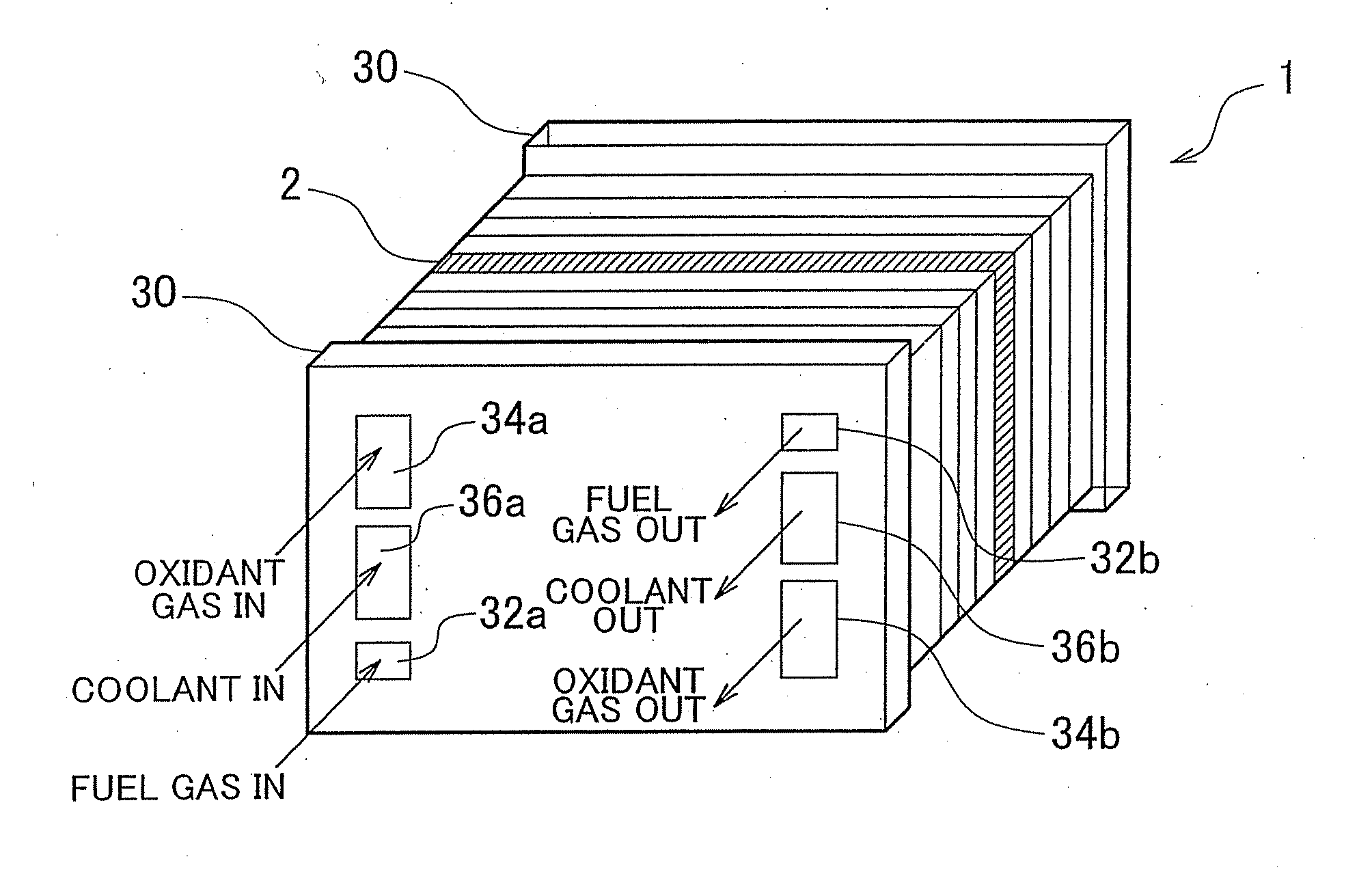
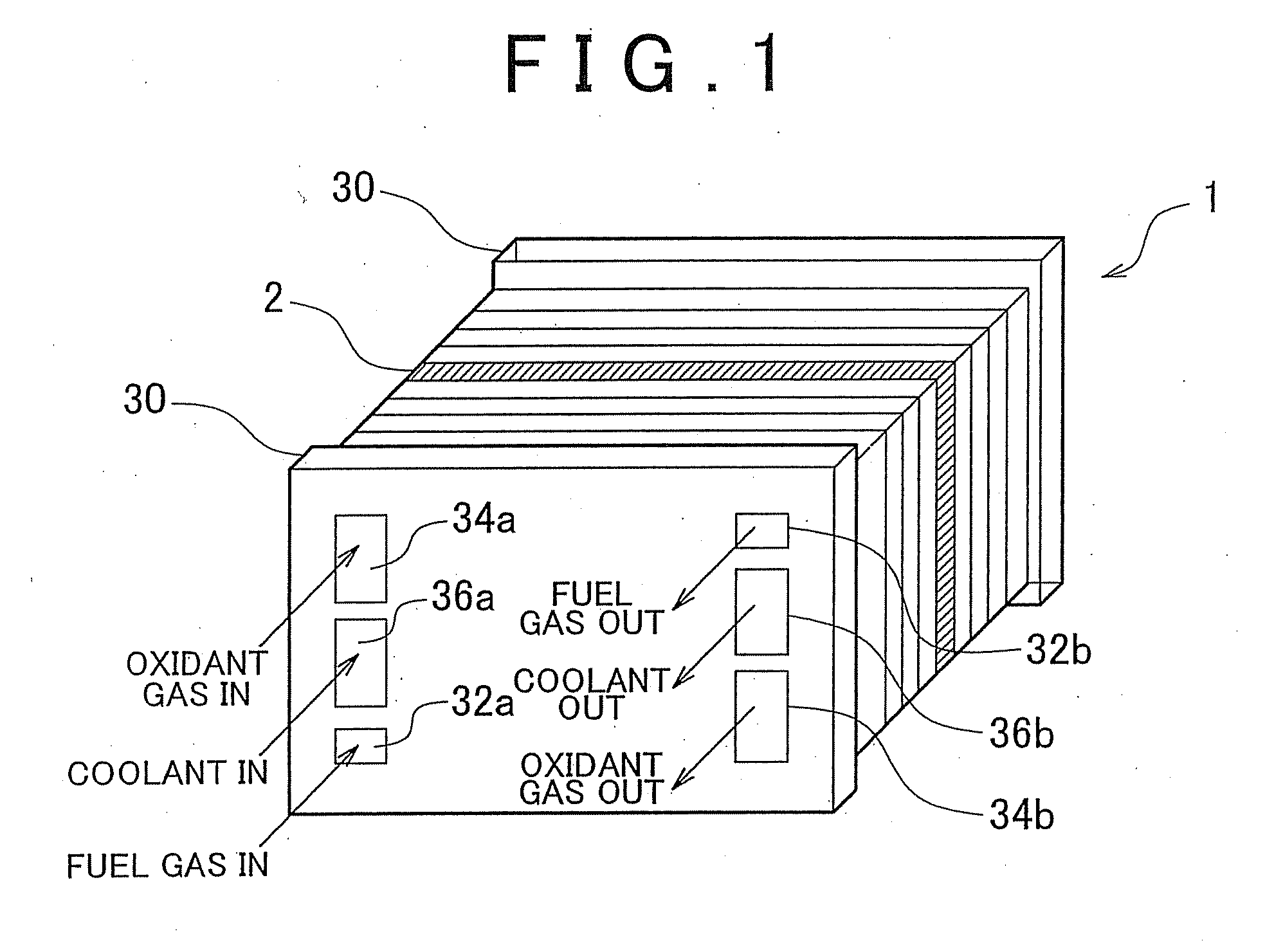
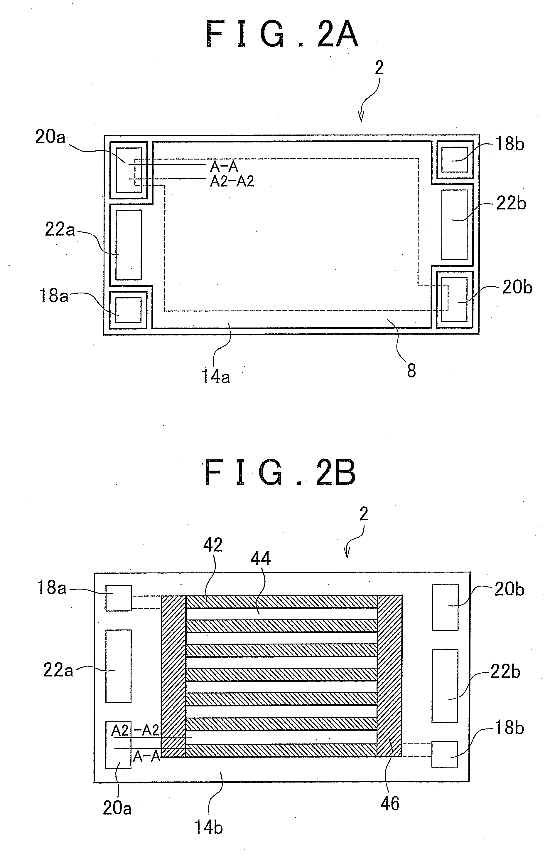
[0029]Hereafter, the invention will be described with reference to FIGS. 1, 2A, 2B, 3A and 3B. FIG. 1 shows a fuel cell stack 1. FIG. 2A is a plan view of a fuel cell 2 (hereinafter also referred to as “cell 2”) viewed from the cathode side. FIG. 2B is a plan view of the cell 2 viewed from the anode side. That is, FIG. 2A shows one side of the cell 2, and FIG. 2B shows the other side of the cell 2. FIG. 3A is a sectional view taken along the line A-A in FIGS. 2A and 2B. FIG. 3B is a sectional view taken along the line A2-A2 in FIGS. 2A and 2B. As shown in FIG. 1, the fuel cell stack 1 is formed by stacking a plurality of unit cells 2. The stacked cells 2 are electrically connected in series. Electric currents obtained through electric power generation at the cells 2 are collected at two current collector plates 30 that are provided at respective ends in a stacking direction of the stacked cells 2. The collected electric currents are supplied to electric apparatuses such as an electr...
second embodiment
[0045]Next, a second embodiment will be described with reference to FIG. 4. Like FIG. 3A, FIG. 4 is a sectional view taken along the line A-A in FIGS. 2A and 2B. Portions the same in structure as those in FIG. 3A will not be described below.
[0046]In the second embodiment, the shield member 16 is not provided at the boundary between the porous passage 8 and the sealing member 12, and the end portion of the cathode electrode 4 is extended in the direction of the oxidant gas supply manifold portion 20a. At the oxidant gas supply manifold portion 20a side, the end portion of the cathode 4 extends further outward, with respect to the cell 2, than the end portion of the sealing member 12. Thus, the cathode 4 covers the electrolyte membrane 3 and the sealing member 12, thereby providing a shielding effect. Note that the feature that the end portion of the cathode electrode 4 extends outward with respect to the cell 2 means that the end portion of the cathode electrode 4 extends outward, wi...
third embodiment
[0048]A third embodiment will be described with reference to FIG. 5. Like FIG. 3A, FIG. 5 is a sectional view taken along the line A-A in FIGS. 2A and 2B. Portions the same in structure as those in FIG. 3A will not be described below.
[0049]The end portion of the porous passage 8 is disposed further inward, with respect to the cell 2, than the end portion of the shield member 16 at the oxidant gas supply manifold portion 20a side. The separator 14a has a projecting portion at a position corresponding to the end portion of the porous passage 8, and the end portion of the porous passage 8 is disposed at a position corresponding to the projecting portion of the separator 14a. Therefore, the oxidant gas supplied through the oxidant gas supply manifold portion 20a is introduced through the end surface and the upper surface of the end portion of the porous passage 8 and is supplied to the membrane electrode assembly 6.
[0050]The separator 14b has a key-like bent portion along the outer peri...
PUM
| Property | Measurement | Unit |
|---|---|---|
| width | aaaaa | aaaaa |
| electric energy | aaaaa | aaaaa |
Abstract
Description
Claims
Application Information
 - R&D
- Intellectual Property
- Life Sciences
- Materials
- Tech Scout
- Unparalleled Data Quality
- Higher Quality Content
- 60% Fewer Hallucinations
Browse by: Latest US Patents, China's latest patents, Technical Efficacy Thesaurus, Application Domain, Technology Topic, Popular Technical Reports.
© 2025 PatSnap. All rights reserved.Legal|Privacy policy|Modern Slavery Act Transparency Statement|Sitemap|About US| Contact US: help@patsnap.com