
Determination of a Magnetic Resonance System Activation Sequence

a magnetic resonance system and activation sequence technology, applied in the field of magnetic resonance system activation sequence determination, can solve the problems of increased risk of image artifact formation, one-dimensional, two-dimensional, multi-dimensional k-space trajectories for selective excitation, and substantially greater complexity, and achieve the effect of rapid and robust calculation of optimized k-space trajectories

Inactive Publication Date: 2013-09-26
SIEMENS HEALTHCARE GMBH
View PDF3 Cites 16 Cited by
  • Summary
  • Abstract
  • Description
  • Claims
  • Application Information

AI Technical Summary

Benefits of technology

The present invention provides a method for determining the optimal sequence of a magnetic resonance system activation and control sequences, which allows for very rapid and robust calculations of k-space trajectories. This leads to better image quality and faster measurements. Additionally, the invention provides a computer program that can be easily integrated into existing control sequence determination devices, allowing for the rapid and robust determination of optimal control sequences. The method also involves sub-sampling the k-space with the aid of the activation sequence, which can accelerate the excitation and measurement process in the case of a pTX system. Overall, the invention improves the speed and quality of magnetic resonance imaging.

Problems solved by technology

In relation to the trajectories that may be used, however, with constant gradients that are used for a simple layer-selective excitation, such one-dimensional, two-dimensional, or multi-dimensional k-space trajectories for selective excitation exhibit a substantially greater complexity.
Due to this greater complexity, there is also an increased risk of artifact formation in the images (e.g., because such pulses may be substantially longer).

Method used


Image

  • Determination of a Magnetic Resonance System Activation Sequence
  • Determination of a Magnetic Resonance System Activation Sequence
  • Determination of a Magnetic Resonance System Activation Sequence

Examples


Embodiment Construction

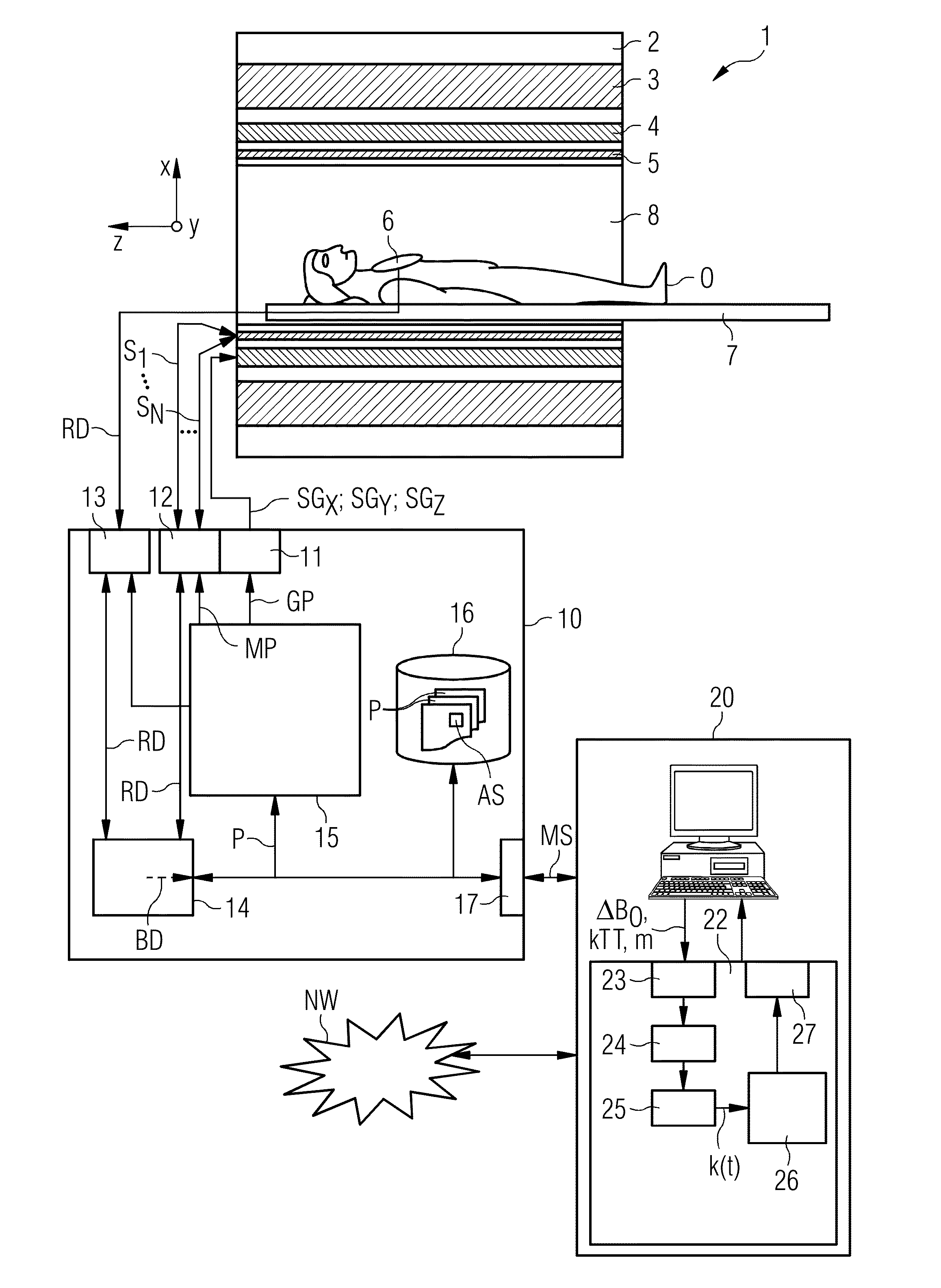
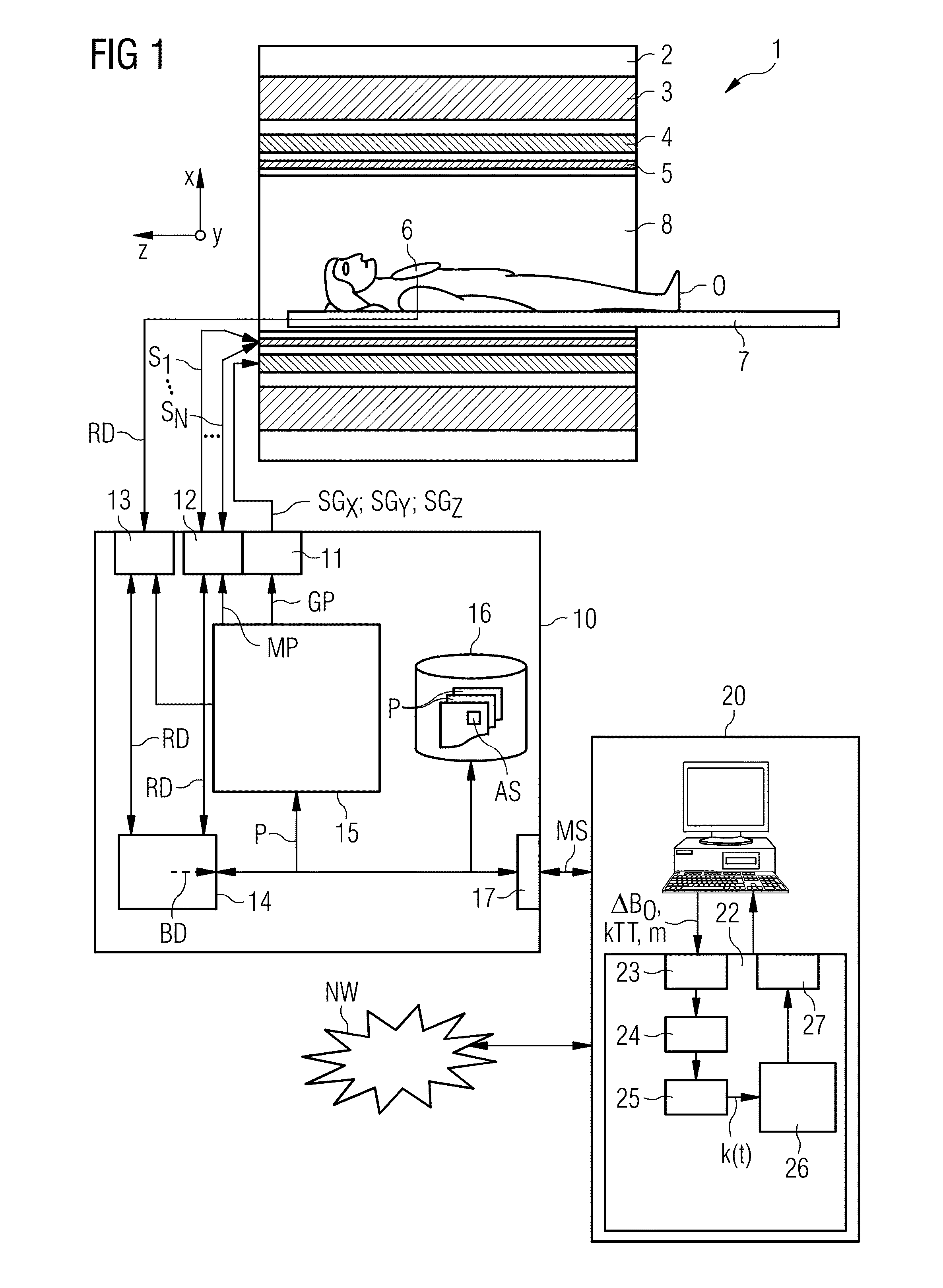
[0052]FIG. 1 shows, in rough diagrammatical form, one embodiment of a magnetic resonance system 1. The magnetic resonance system 1 includes an actual magnetic resonance scanner 2 with an examination space 8 or patient tunnel disposed in the actual magnetic resonance scanner 2. A couch 7 may be moved into the patient tunnel 8, such that an object O to be examined (e.g., a patient / test subject) lying on the couch 7 may be positioned during an examination in a specific position inside the magnetic resonance scanner 2 relative to the magnet system and high-frequency system arranged inside. The object O may also be moved during a measurement between different positions.

[0053]Major components of the magnetic resonance scanner 2 are a basic field magnet 3, a gradient system 4 with magnetic field gradient coils in order to apply magnetic field gradients, as desired, in the x-, y- and z-directions, and a whole-body high-frequency coil 5. The reception of the magnetic resonance signals induce...


PUM


Abstract

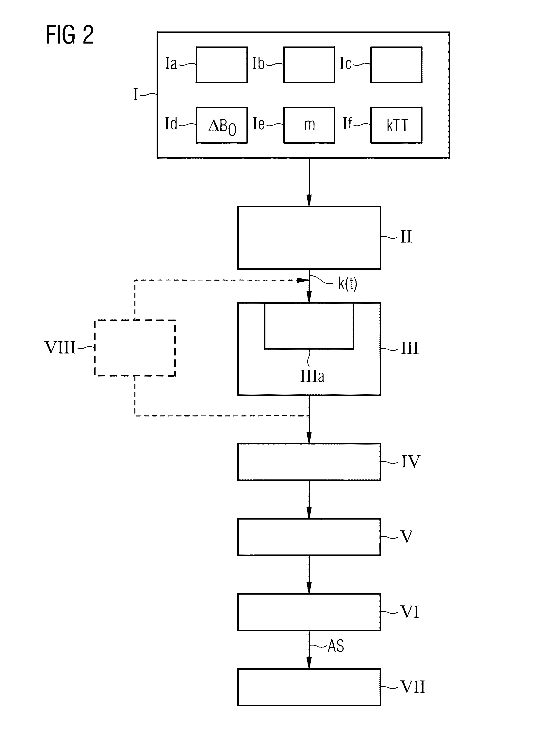
A method and a control sequence determination device for the determination of a magnetic resonance system activation sequence including at least one high-frequency pulse sequence to be transmitted by a magnetic resonance system are provided. A current B0 map and optionally a target magnetization are acquired. In addition, a k-space trajectory type is determined. An error density is calculated in a k-space based on the current B0 map and optionally based on the target magnetization using an analytic function. This analytic function defines an error density in the k-space as a function of the current B0 map and optionally the target magnetization. Taking account of the error density in the k-space, a k-space trajectory of the specified k-space trajectory type is determined. The high-frequency pulse sequence is determined for the k-space trajectory in an HF pulse optimization process.

Description

[0001]This application claims the benefit of DE 10 2012 204 401.9, filed on Mar. 20, 2012, and DE 10 2012 212 376.8, filed on Jul. 16, 2012, which are hereby incorporated by reference.BACKGROUND[0002]The present embodiments relate to a method and a control sequence determination device for the determination of a magnetic resonance system activation sequence.[0003]In a magnetic resonance tomography system (e.g., magnetic resonance system), the body that is to be examined may be subjected to a relatively high main magnetic field (e.g., the B0 field; 3 or 7 Tesla), with the aid of a main field magnetic system. In addition, a magnetic field gradient is applied with the aid of a gradient system. Using a high-frequency transmitter system, high-frequency excitation signals (HF signals) are emitted by suitable antenna devices, the intention of which is that the nuclear spins of specific atoms or molecules, excited to resonance by this high-frequency field, are tilted by a defined flip angle...

Claims


Application Information

Patent Timeline
IPC IPC(8): G01R33/44G01R33/38
CPCG01R33/38G01R33/443G01R33/56563G01R33/4836G01R33/5612G01R33/4833A61B5/055G01R33/20G01R33/36
Inventor PFEUFFER, JOSEFSCHNEIDER, RAINER
Owner SIEMENS HEALTHCARE GMBH
Learn More