Silencer for exhaust systems
- Summary
- Abstract
- Description
- Claims
- Application Information
AI Technical Summary
Benefits of technology
Problems solved by technology
Method used
Image
Examples
first embodiment
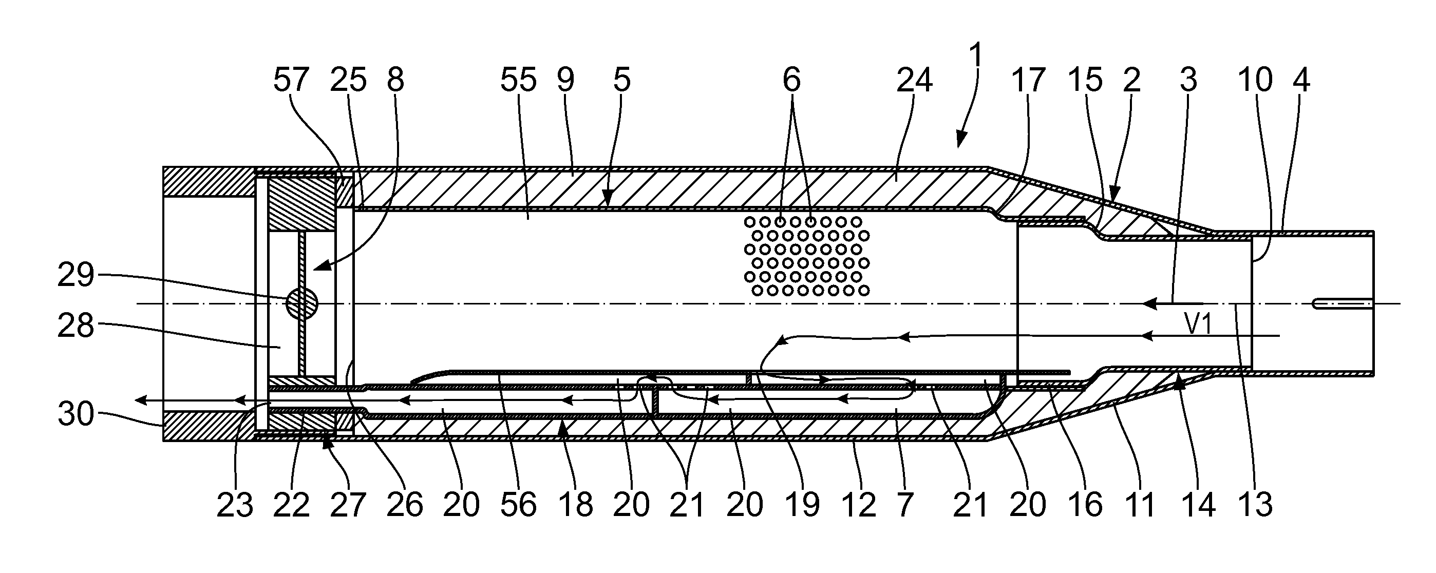
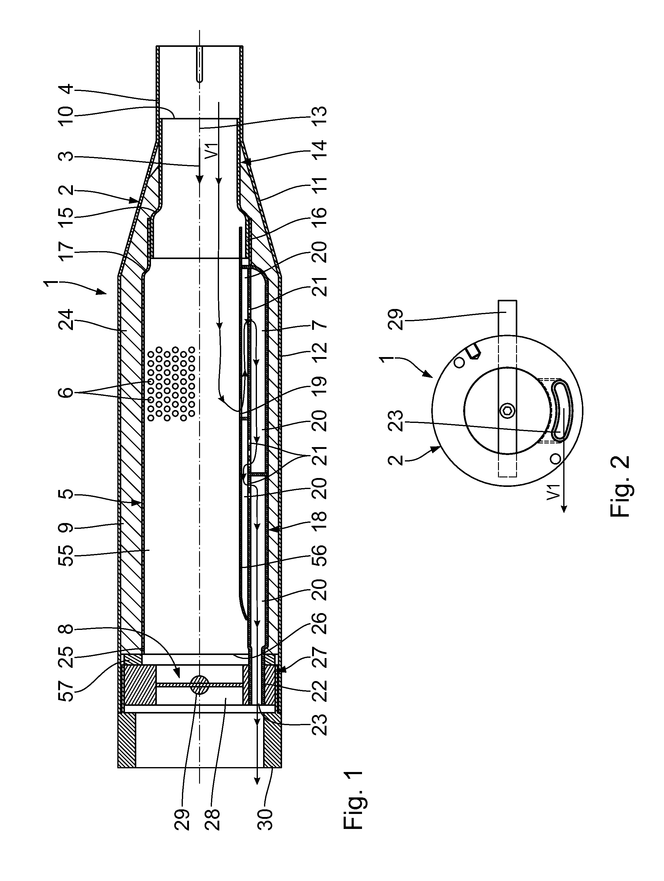
[0081]With reference to FIGS. 1 to 4, the invention will be described below. A silencer 1 for use in exhaust systems of motor vehicles, in particular motorcycles, has a silencer housing 2, which preferably tapers counter to a main flow direction 3 of exhaust gas and is rigidly connected to a connection piece 4. The silencer housing 2 may, however, also have a corresponding different geometric shape. The connection piece 4 can be attached to a combustion engine of a motor vehicle or another silencer 1. The silencer housing 2 and the connection piece 4 may be configured in one piece or as separate components. Arranged within the silencer housing 2 is an exhaust gas flow pipe 5, which runs straight, peripherally has perforation openings 6, at least in regions, and laterally delimits an exhaust gas flow channel 55. Furthermore, a bypass channel 7, which has a flow connection to the exhaust gas flow pipe 5 or the exhaust gas flow channel 55 and substantially runs along the latter, extend...
fourth embodiment
[0104]With reference to FIGS. 12 and 13, the invention will be described below. This embodiment is similar to the embodiment according to FIGS. 10 and 11. The exhaust gas through-openings 32 in the inner pipe 31d are now arranged in a front region thereof. Furthermore, further exhaust gas through-openings 32 are provided in a rear region of the inner pipe 31d.
[0105]The bypass body 18d predetermines a flow channel 7d, which is, for example, meandering. The flow chambers 20d are again connected in series and extend parallel to the main flow direction 3. The adjustment body 8 is arranged in the inner pipe 31d adjacent to the flow chambers 20d. The adjustment body 8 is provided between the exhaust gas inlet opening 10 and the exhaust gas outlet opening 26 of the exhaust gas flow pipe 5. It is arranged approximately centrally between the openings 10, 26. The exhaust gas can thus be guided upstream of the adjustment body 8 through the exhaust gas through-openings 32 from the inner pipe 3...
fifth embodiment
[0109]With reference to FIGS. 14 to 17, the invention will be described below. In contrast to the previous embodiments, the silencer housing 2e is substantially oval in cross-section here. A silencing takes place in the silencer 1e by means of reflection and resonance.
[0110]The silencer 1e has a connection piece 4e, which is circular ring-shaped in cross-section.
[0111]The silencer housing 2e widens irregularly over the widening region 11e. The silencer housing 2e runs substantially further downward than upward from the connection piece 4e, so the connection piece 4e is located in an upper region of the silencer housing 2e.
[0112]The exhaust gas flow pipe 5e, which initially widens downwardly from the connection piece 4e in the main flow direction 3, furthermore adjoins the connection piece 4e. Perforation openings 6 are provided in the exhaust gas flow pipe 5e, at least in an upstream region of the exhaust gas flow pipe 5e.
[0113]Provided between the silencer housing 2e and the exha...
PUM
 Abstract
Description
Claims
Application Information
 - R&D
- Intellectual Property
- Life Sciences
- Materials
- Tech Scout
- Unparalleled Data Quality
- Higher Quality Content
- 60% Fewer Hallucinations
Browse by: Latest US Patents, China's latest patents, Technical Efficacy Thesaurus, Application Domain, Technology Topic, Popular Technical Reports.
© 2025 PatSnap. All rights reserved.Legal|Privacy policy|Modern Slavery Act Transparency Statement|Sitemap|About US| Contact US: help@patsnap.com


