
Magnetic Logic Units Configured as an Amplifier

a technology of magnetic logic and amplifier, which is applied in the direction of galvano-magnetic amplifiers, digital storage, instruments, etc., can solve the problems of limiting the switching speed and bandwidth of these amplifiers, limiting the power added efficiency of these amplifiers, and amplifiers with significant coupling capacitance between input and outpu

Active Publication Date: 2013-09-19
CROCUS TECHNOLOGY
View PDF2 Cites 5 Cited by
  • Summary
  • Abstract
  • Description
  • Claims
  • Application Information

AI Technical Summary

Benefits of technology

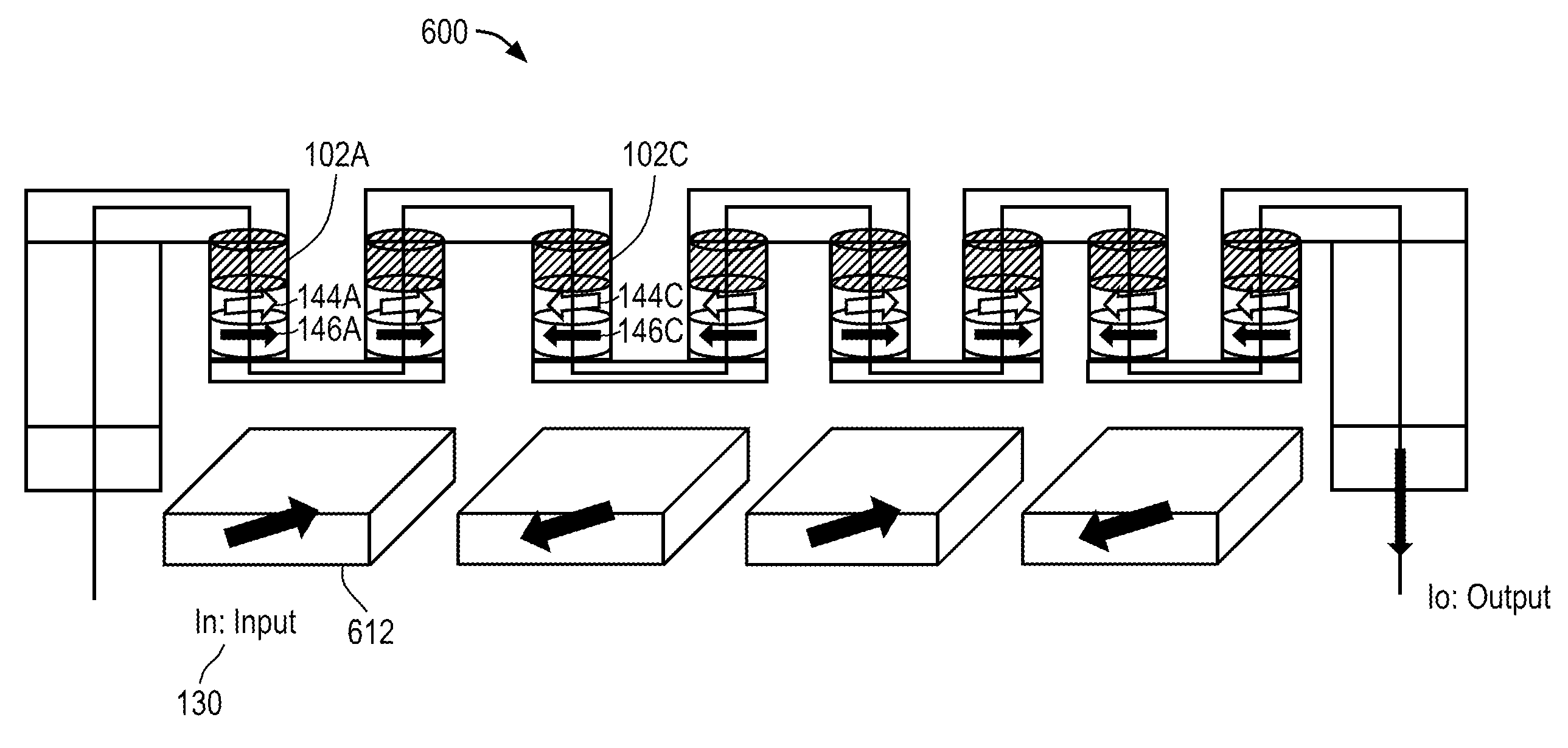
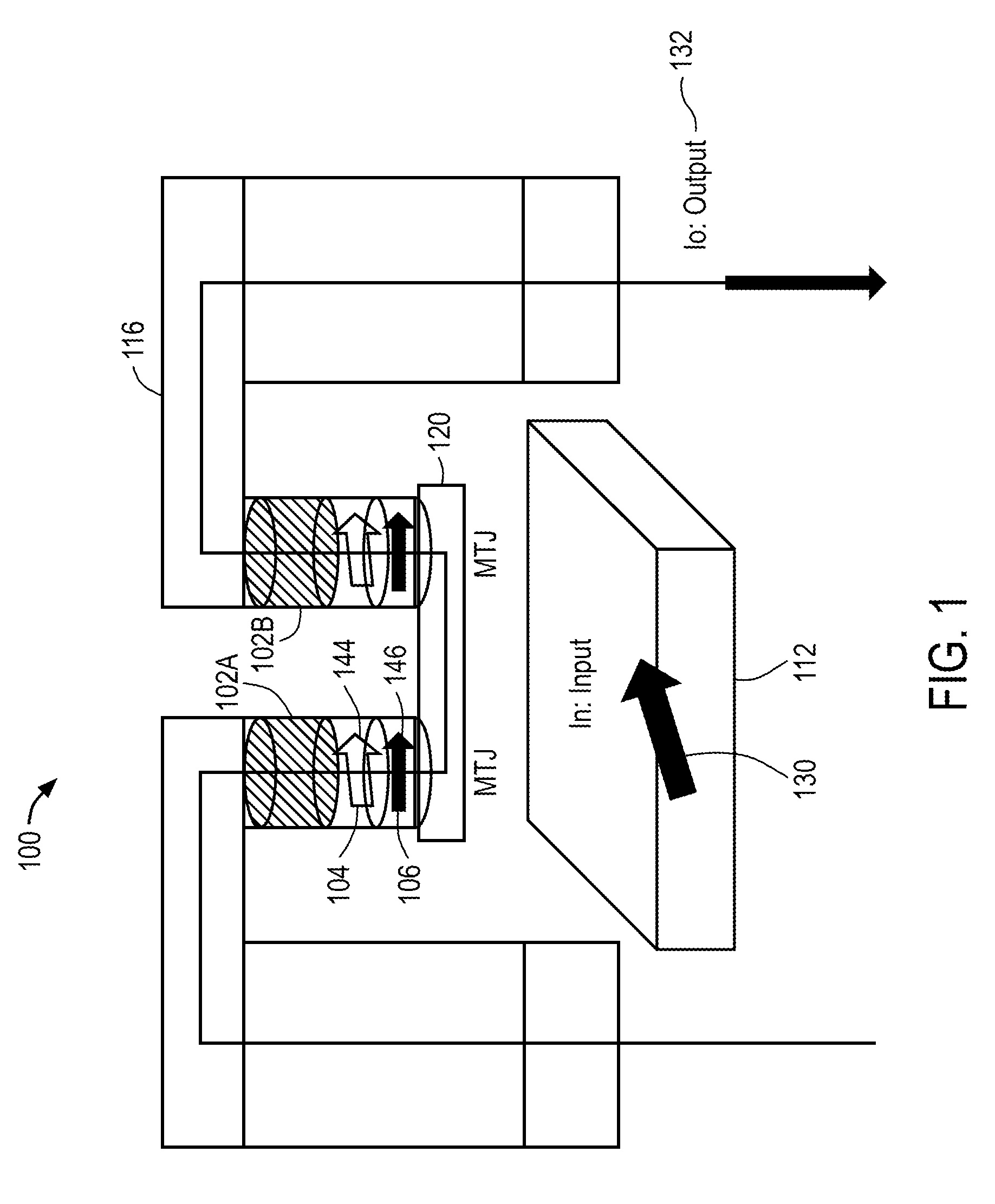
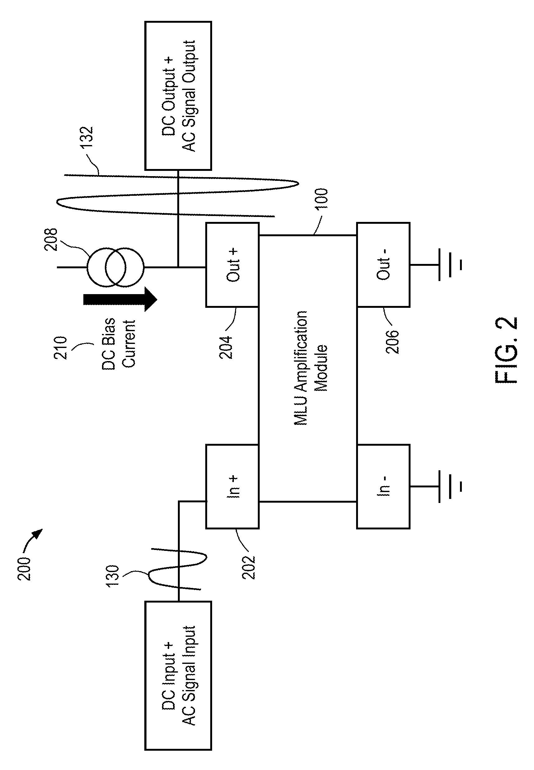
The invention is about an apparatus that includes a circuit and a field line. The circuit has a magnetic tunnel junction made up of a storage layer and a sense layer, and the field line generates a magnetic field based on an input signal. The resistance of the magnetic tunnel junction changes based on the magnetic field. The apparatus amplifies the input signal and generates an output signal that changes in response to the resistance of the magnetic tunnel junction. The technical effect of this invention is to provide a device that can detect and measure magnetic fields with high precision.

Problems solved by technology

These conventional amplifiers may have significant coupling capacitance between the input and the output, such as due to the Miller effect.
This capacitance may limit switching speed and bandwidth of these amplifiers.
In addition, the power added efficiency of these amplifiers may be limited by transistor characteristics.
Moreover, these amplifiers may be fabricated using complementary MOS (CMOS) processes with upwards of twelve layers, which adds to both cost and size of these amplifiers.

Method used


Image

  • Magnetic Logic Units Configured as an Amplifier
  • Magnetic Logic Units Configured as an Amplifier
  • Magnetic Logic Units Configured as an Amplifier

Examples


Embodiment Construction

Definitions

[0020]The following definitions apply to some of the aspects described with respect to some embodiments of the invention. These definitions may likewise be expanded upon herein.

[0021]As used herein, the singular terms “a,”“an,” and “the” include plural referents unless the context clearly dictates otherwise. Thus, for example, reference to an object can include multiple objects unless the context clearly dictates otherwise.

[0022]As used herein, the term “set” refers to a collection of one or more objects. Thus, for example, a set of objects can include a single object or multiple objects. Objects of a set also can be referred to as members of the set. Objects of a set can be the same or different. In some instances, objects of a set can share one or more common characteristics.

[0023]As used herein, the terms “substantially” and “substantial” refer to a considerable degree or extent. When used in conjunction with an event or circumstance, the terms can refer to instances i...


PUM


Abstract

An apparatus includes a circuit and a field line. The circuit includes a magnetic tunnel junction including a storage layer and a sense layer. The field line is configured to generate a magnetic field based on an input signal, where the magnetic tunnel junction is configured such that a magnetization direction of the sense layer and a resistance of the magnetic tunnel junction vary based on the magnetic field. The circuit is configured to amplify the input signal to generate an output signal that varies in response to the resistance of the magnetic tunnel junction.

Description

CROSS-REFERENCE TO RELATED APPLICATION[0001]The present application claims the benefit of U.S. Provisional Application No. 61 / 600,548, filed on Feb. 17, 2012, the disclosure of which is incorporated herein by reference in its entirety.FIELD OF THE INVENTION[0002]The invention relates generally to magnetic logic units and, more particularly, to magnetic logic units configured as an amplifier.BACKGROUND[0003]Traditional active devices used in power amplifiers are typically based on bipolar transistors, metal oxide semiconductor (MOS) field effect transistors, GaAs heterojunction bipolar transistors (HBT), and / or GaN transistors connected together to form a structure large enough to handle desired output power levels. Matching passive component circuits may be used to extract the AC power out for high frequency applications.[0004]These conventional amplifiers may have significant coupling capacitance between the input and the output, such as due to the Miller effect. This capacitance m...

Claims


Application Information

Patent Timeline
IPC IPC(8): H03F15/00
CPCG11C11/16H03F15/00G11C11/15G11C11/02G11C11/14H03F19/00
Inventor CAMBOU, BERTRAND F.LEE, DOUGLAS J.MACKAY, KEN
Owner CROCUS TECHNOLOGY
Learn More