Webbing retractor
a retractor and webbing technology, applied in the direction of belt retractors, vehicle safety belts, vehicle components, etc., can solve the problem of potential generation of unwanted burrs
- Summary
- Abstract
- Description
- Claims
- Application Information
AI Technical Summary
Benefits of technology
Problems solved by technology
Method used
Image
Examples
first embodiment
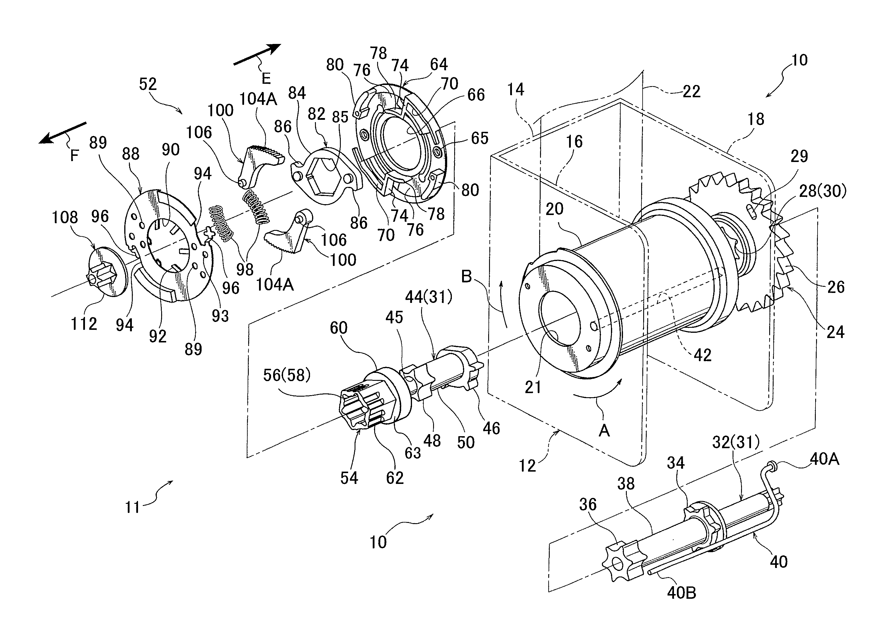
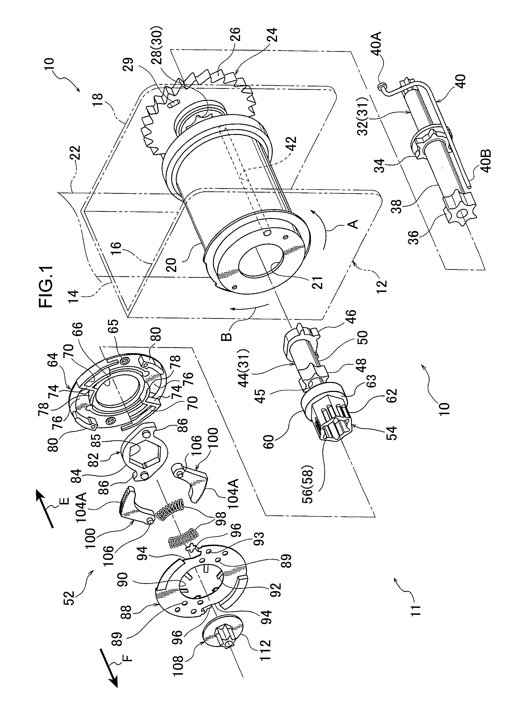
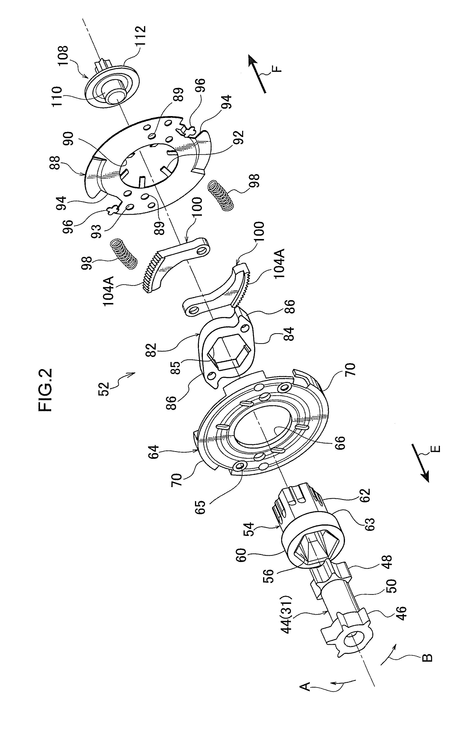
[0048]A webbing retractor 10 relating to a first embodiment of the present invention is described hereinafter by using FIG. 1 through FIG. 11.
[0049]As shown in FIG. 1 through FIG. 5, the webbing retractor 10 relating to the present first embodiment has a frame 12, a webbing 22, a webbing take-up shaft 11, and a switching mechanism 120.
[0050]As shown in FIG. 1, the frame 12 has a plate-shaped back plate 14 that is fixed to the vehicle body. Leg pieces 16, 18 extend substantially orthogonally from the vehicle transverse direction both end portions of the back plate 14, and the frame 12 is formed in a substantially concave shape as seen in plan view. Note that a known locking mechanism is mounted to the outer side of the leg piece 18. Further, the webbing 22 is applied to the body of a passenger, and is formed in an elongated belt shape.
[0051]Structure of Webbing Take-Up Shaft 11
[0052]The webbing take-up shaft 11 has a spool 20, a lock gear 24 serving as a lock section, a main torsion ...
second exemplary embodiment
[0118]FIG. 12 is a perspective view corresponding to FIG. 7 that illustrates a portion of a clutch base 82′ that is a configuration member of a webbing retractor according to a second exemplary embodiment of the present invention. FIG. 13 is a cross-section taken along line 13-13 of FIG. 12. This exemplary embodiment is configured basically the same as the first exemplary embodiment, but ribs 91′ of the clutch base 82′ differ from the ribs 91 according to the first exemplary embodiment. The ribs 91′ are configured basically the same as the ribs 91 of the first exemplary embodiment, except that sloping faces 91A′ that are the end faces of the ribs 91′ on the opposite side to the press insertion portion 62 press insertion direction (to the arrow F direction of FIG. 13 and FIG. 14) are provided separated in the press insertion direction from a hole edge portion 84B1 (abutted portion) of a press insertion hole 85 of the clutch base 82′. Thus in the press-inserted state of the press inse...
third exemplary embodiment
[0121]FIG. 15 is a cross-section illustrating a configuration of part of a webbing retractor according to a third exemplary embodiment of the present invention. In the present exemplary embodiment, a press insertion portion 202 (hole portion) is provided at an axial center portion of a spool 200 that serves as a press insertion member is press-inserted (press-fit) from an opening side over a pressed insertion portion 206 that is provided at one axial direction end portion of a torsion shaft 204 serving as a pressed insertion member. The torsion shaft 204 is formed from a metal material harder than the spool 200. Ribs 208 are also provided to an outer peripheral face of the pressed insertion portion 206 (a face that faces the press insertion portion 202). An end face of the rib 208 on the opposite side to the press insertion direction of the press insertion portion 202 (to the arrow G direction of FIG. 15) is configured as a sloping face 208A (C (chamfer) face) that slopes along the ...
PUM
 Abstract
Description
Claims
Application Information
 - R&D
- Intellectual Property
- Life Sciences
- Materials
- Tech Scout
- Unparalleled Data Quality
- Higher Quality Content
- 60% Fewer Hallucinations
Browse by: Latest US Patents, China's latest patents, Technical Efficacy Thesaurus, Application Domain, Technology Topic, Popular Technical Reports.
© 2025 PatSnap. All rights reserved.Legal|Privacy policy|Modern Slavery Act Transparency Statement|Sitemap|About US| Contact US: help@patsnap.com


