
Spotting plate and process for its production

a technology applied in the field of spotting plates and process for its production, can solve the problems of increasing the risk of damage to the pipetting head, difficult structure, and time-consuming process, and achieves easy and more specific binding, high binding capacity, and increased binding capacity of the polymeric substrate.

Inactive Publication Date: 2013-09-12
SCIENION GMBH +1
View PDF19 Cites 8 Cited by
  • Summary
  • Abstract
  • Description
  • Claims
  • Application Information

AI Technical Summary

Benefits of technology

The present invention relates to a reaction chamber assembly for ultrasonic welding, which uses sound waves to create a strong bond between parts made of polymeric materials. The process involves transmitting sound waves to the parts to be bonded and applying pressure to bring them into contact. Ultrasonic welding is faster than other methods and can be used with a variety of polymeric materials. The reaction chamber assembly is designed to be easily handled by automated devices. The technical effects include faster and stronger bonding with improved efficiency and flexibility.

Problems solved by technology

Although the standard structure of the plates has facilitated such automated processing, at the same time this structure presents challenges with regard to certain procedures.
Depending on the kind of microarray printed it might be necessary to move the pipetting head over 100 times into one well which makes this process very time consuming.
Furthermore, these movements increase the risk of damaging the pipetting head.
However, these techniques bear the disadvantage of leakiness of single wells and thus the risk of cross contamination.
Further, the used adhesives or gasket materials can interfere massively with assay reagents or contain toxic solvents which are not compatible with sensitive biological applications.
However, it is very laborious and uneconomical to spot one plate with many different microarrays.

Method used


Image

  • Spotting plate and process for its production
  • Spotting plate and process for its production
  • Spotting plate and process for its production

Examples


example preparation

of a Microtiter Plate in a Batch Process

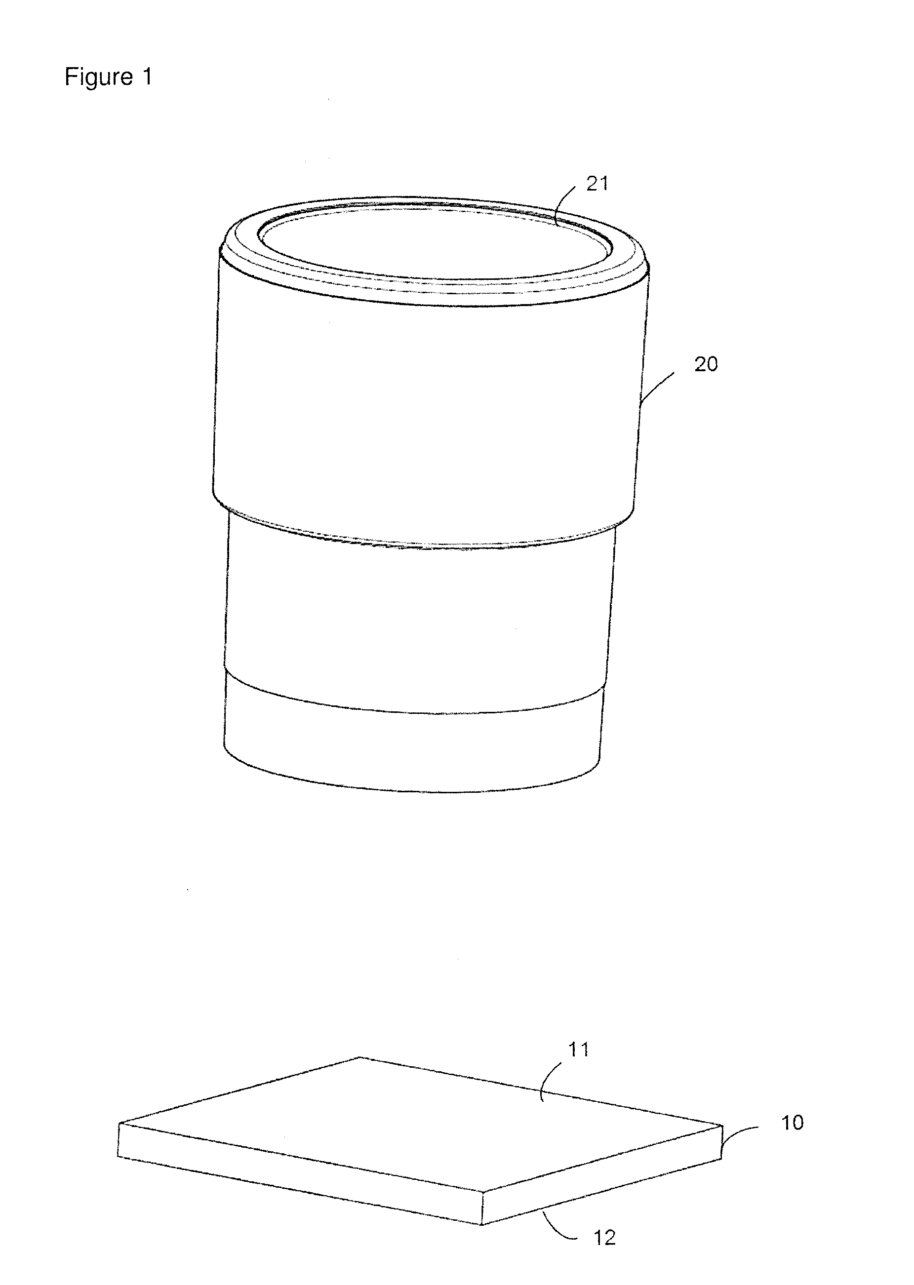
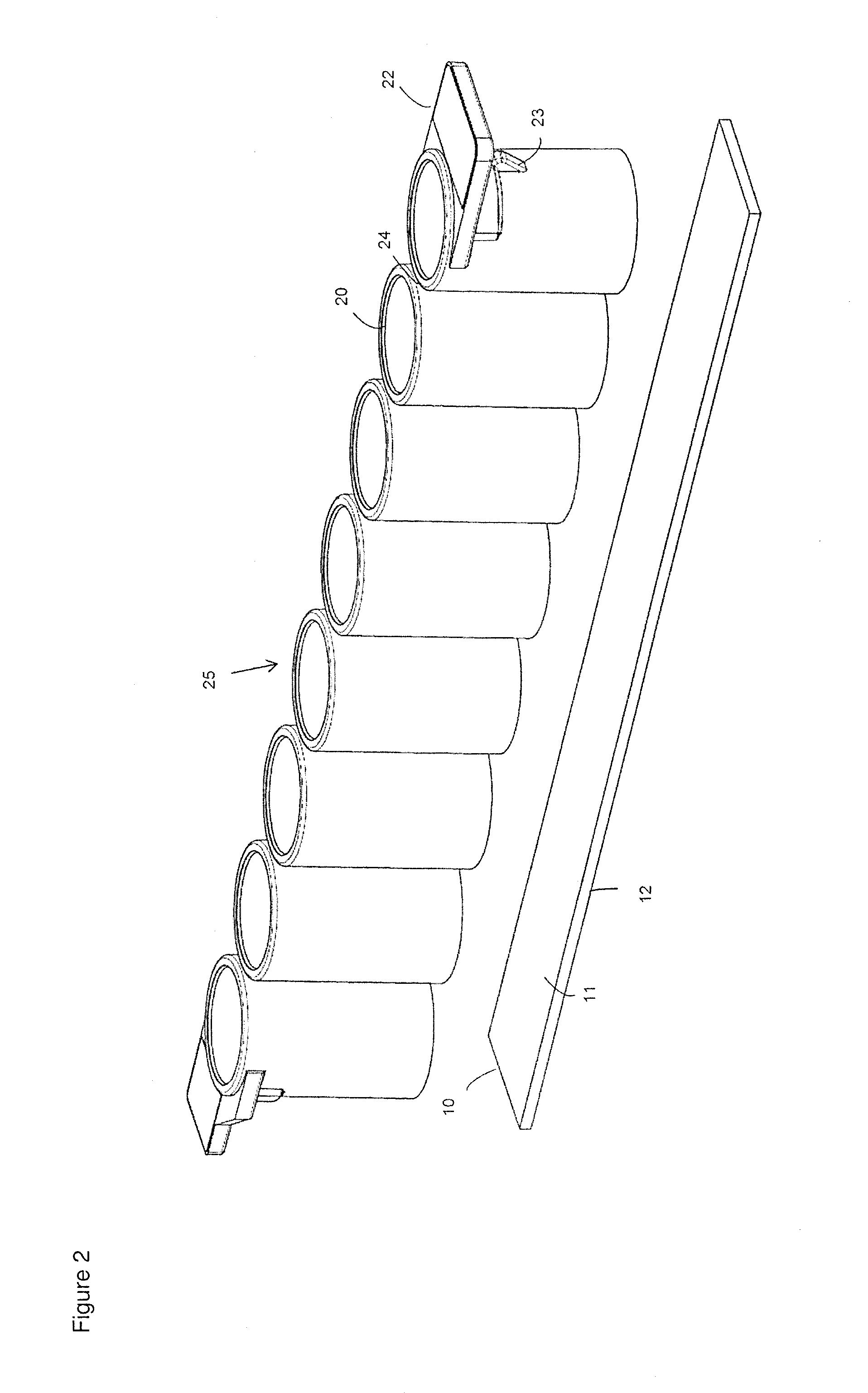
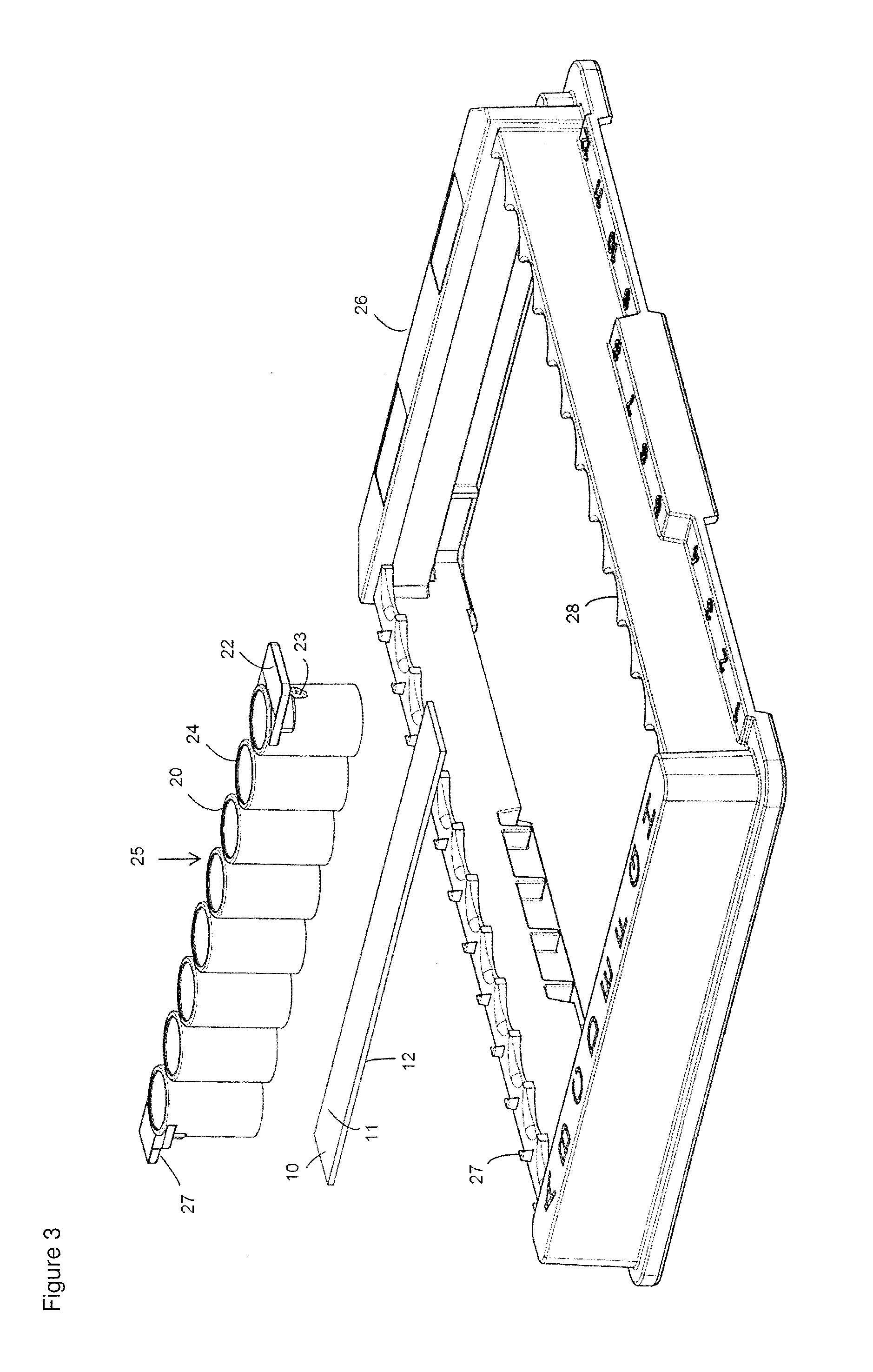
[0085]For the preparation of a reaction chamber assembly in form of a microtiter plate 40 a polymeric flat substrate plate 10 having a reaction surface 11 and a bottom surface 12 is used. The substrate 10 has a size according to SBS standard ANSI / SBS 4-2004 appropriate to accommodate a superstructure 40, here a microtiter plate with bottomless reaction chambers 20.

[0086]The flat substrates are first analysed for the homogenity of their surfaces with a fluorescence scanner at 532 nm. The averaged background fluorescence at 96 positions is measured and averaged. In a second quality control the contact angle with water is measured at 10 positions.

[0087]Afterwards, the biological agent to be loaded or spotted onto the substrate plates 10 are prepared in their respective buffer solutions and positioned in the “source tube” or “source plate” location of a printing system or spotter, for example a sciFLEXARRAYER. The printing system or spotter or sci...


PUM

PropertyMeasurementUnit
thicknessaaaaaaaaaa
speedaaaaaaaaaa
diameteraaaaaaaaaa

Abstract

A process for the production of a reaction chamber assembly, wherein a flat substrate and bottomless reaction chambers are provided, the substrate is first loaded with a biological agent and then the bottomless reaction chambers are bonded glue-free to the substrate, in particular through laser bonding, and liquid-tight reaction chambers, for instance individual wells, individually connected wells, such as strips, or wells in the form of a microtiter plate, are obtained. The present invention further provides a kit comprising a substrate suitable for being loaded with at least one biological agent and at least one bottomless reaction chamber, wherein the kit is suitable for glue-free bonding of the bottomless reaction chamber to the substrate.

Description

BACKGROUND OF THE INVENTION[0001]The present invention relates to a process for the production of a reaction chamber assembly and to a kit comprising components of the reaction chamber assembly.[0002]Multiwell or microtiter plates cover a broad spectrum of biological, chemical and pharmacological laboratory uses. For high throughput screening as well as diagnostic methods such plates are mostly produced in one piece by injection moulding. Especially as a result of high throughput applications auxiliary automatic and robotic instrumentation has been developed and the dimensions of the plates were standardised. Some analytical or diagnostic applications of multiwell or microtiter plates involve attachment or immobilisation of biological agents or probes to a surface within the wells, mostly the bottom surface, and the performance of one or more reactions in the wells followed by some sort of quantitative and / or qualitative analytical process. For example, the biological agents or prob...

Claims


Application Information

Patent Timeline
Patent Type & Authority Applications(United States)
IPC IPC(8): B01J19/00
CPCB01L3/508B29C66/93431B01L9/523B29C65/08B29C65/16B01L2200/025B01L2200/028B01L2200/0689B01L2200/12B01L2300/0819B01L2300/0829B01L2300/0851B01J19/0046B29C66/9534B29C65/1635B29C65/1661B29C66/028B29C66/112B29C66/114B29C66/53461B29C66/71B29C66/712B29C66/7352B29L2031/756B29C66/929B29C66/939B29C66/949B01L3/50855B29C66/91645B29K2025/06B29K2023/12B29K2069/00B29K2077/00B29K2055/02B29K2033/12B29K2025/08B29K2023/38B29C65/02B29K2067/00B29K2023/18
Inventor KNEBEL, GUENTHEREICKHOFF, HOLGER
Owner SCIENION GMBH
Learn More