
Treatment of industrial water systems

Inactive Publication Date: 2013-09-12
ECOLAB USA INC
View PDF13 Cites 43 Cited by
  • Summary
  • Abstract
  • Description
  • Claims
  • Application Information

AI Technical Summary

Benefits of technology

The invention is a method for controlling treatment of an industrial water system using a device that measures a parameter of the system, adjusts a treatment protocol based on the measurement, and delivers a concentrated treatment chemical to the system. This method can be repeated for multiple parameters and active ingredients to achieve efficient and effective treatment of the industrial water system.

Problems solved by technology

A limitation of these control methods is that none of these systems measure the treatment product concentration directly online, so if there is a mechanical problem, for example, if a pump fails, a drum empties, or high, low or unknown blowdown occurs, system volume changes or makeup water quality changes; the correct treatment product concentration is not maintained.
Because this problem is common, typically industrial water systems are either overfed to ensure the level of treatment product in the system does not drop too low as a result of high variability in product dosage, or the treatment product is unknowingly underfed.
Both overfeeding and underfeeding of treatment product are undesirable due to cost and performance drawbacks.
Those who produce additive blends encounter several issues when blending (“make-clown” or “making-down”) a new additive blend or package.
First, the cost of formulating a new additive blend or package can be expensive.
Such formulation and re-formulation requires significant man-hours.
Second, the make-down of additive blends and packages at full strength can be dangerous.
The additives, when blended at full strength, may release heat or fumes.
Additionally, because the blend will likely sit in storage for a lengthy period of time, the blend may require the addition of costly halogen- or photo-stable dyes as tracers.

Method used


Image

  • Treatment of industrial water systems
  • Treatment of industrial water systems
  • Treatment of industrial water systems

Examples


example 1

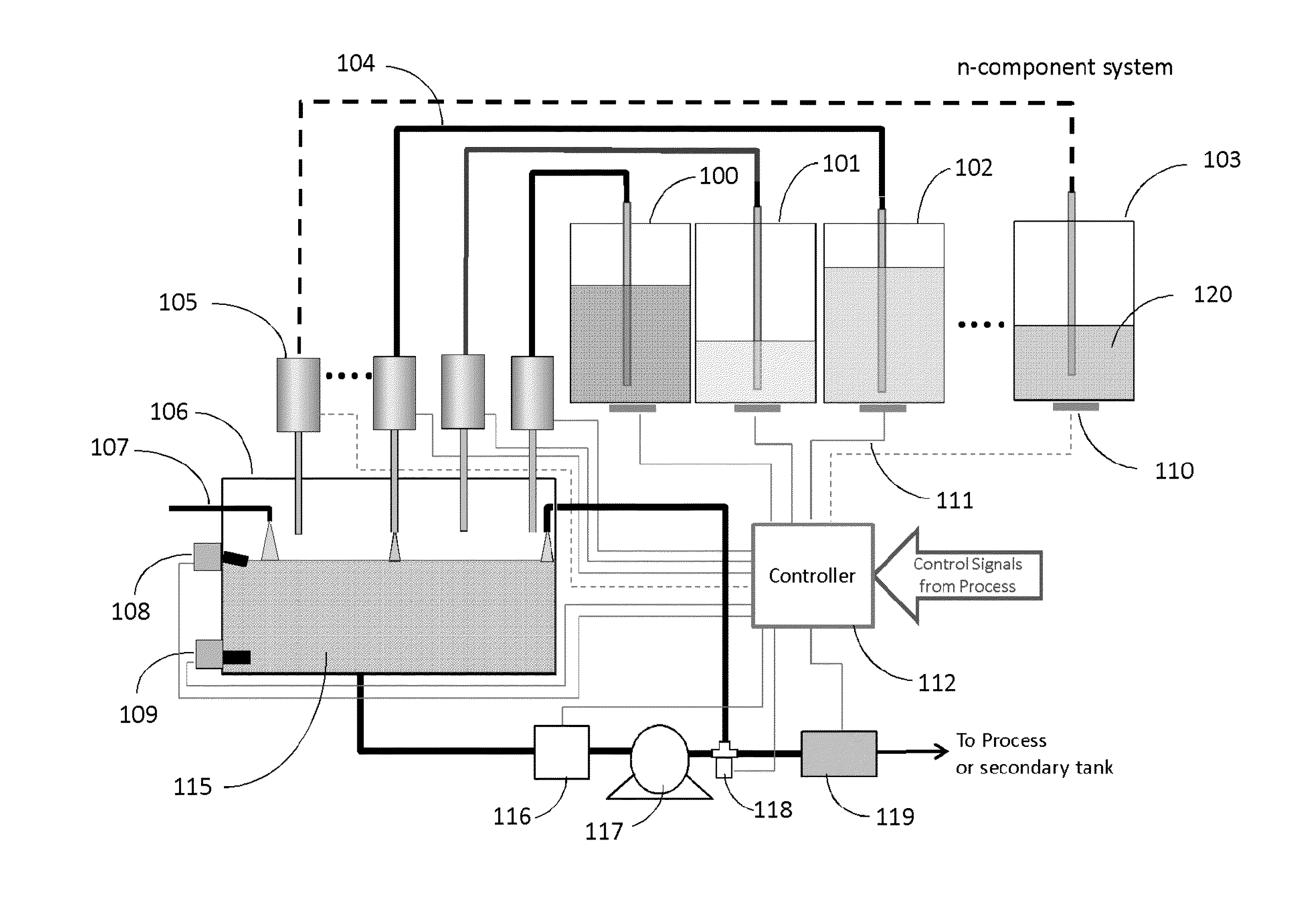
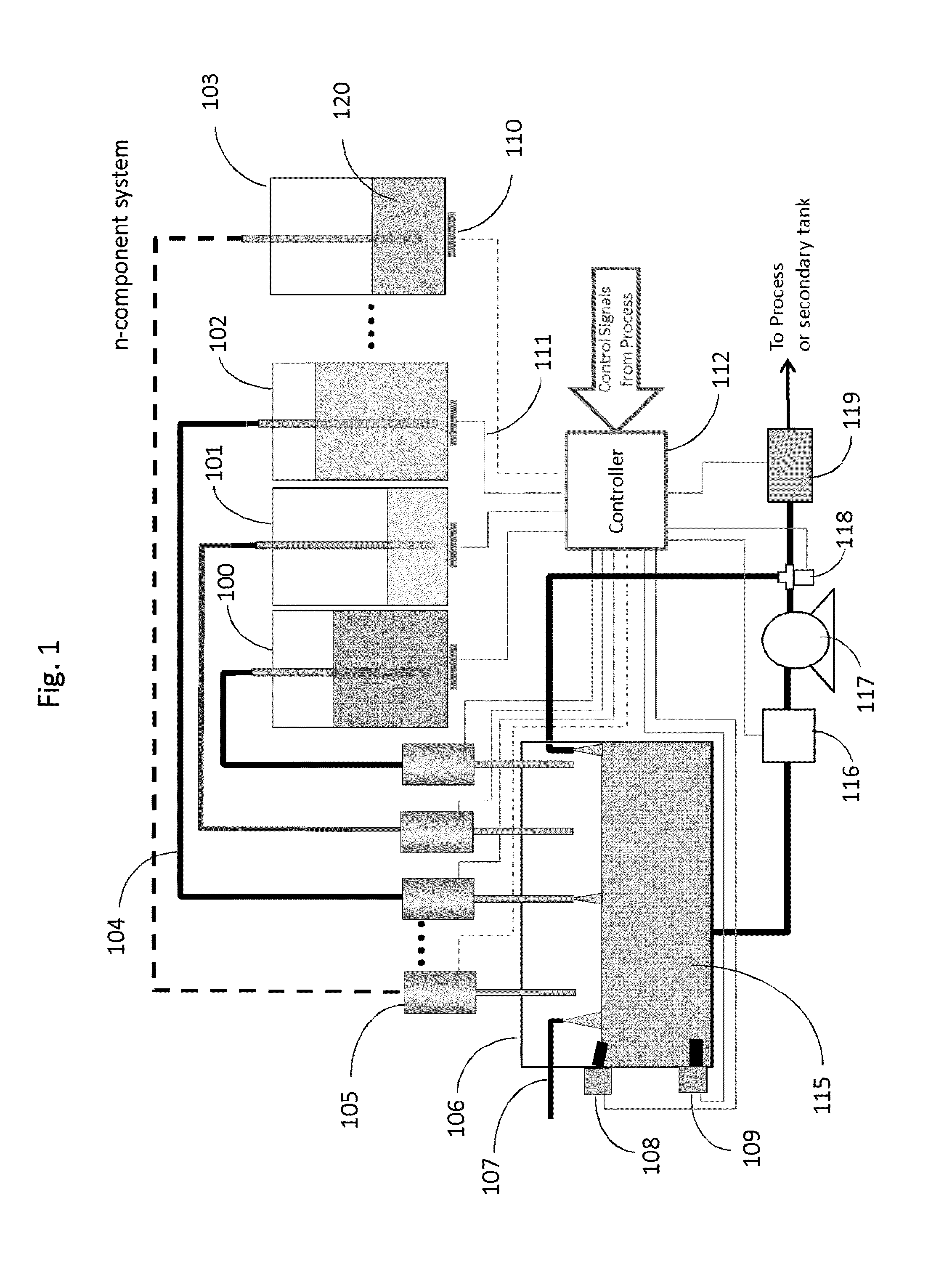
[0052]The first example illustrates injection of the additive package made up from a set of different actives blended in a holding vessel at a predetermined composition for a given batch. Once the additive package is made it can then be dispensed into the process stream. The composition of the additive package is adjusted during the blending step by controlling the individual actives dispensed to the holding vessel. A schematic layout is shown in FIG. 1 for an n-component delivery system. The concentrated actives used in formulating the blend are isolated from one another by containers 100, 101, 102, and n-container 103. The containers can be any suitable material either hard wall or flexible, e.g., polymer bag, that is chemically compatible with the concentrated active. The containers can be modular allowing the user to easily remove and replace the container with the same or different active component, thus providing added flexibility in the composition of the additive package. A ...

example 2

[0062]In the previous example, multiple component monitoring requires a fluorometer having different excitation source wavelengths and detection channels. An alternative approach of the invention is based on monitoring the fluorescence from one component during sequential steps of adding the different active components. For example, to construct the additive package listed in Table 1 the steps listed in Table 2 can be followed to make a 1.0-liter blend. Using THSP as the baseline fluorescence signal the additive package is constructed by measuring the change in the THSP signal. Because THSP is initially highly concentrated the fluorescence signal is nonlinear, as shown in FIG. 3 for the integrated intensity collected using a bifurcated fiber optic probe. For this example, one fiber optic leg supplies the excitation light at 365 nm that propagated through fiber and exits the probe which is submerged into the fluid. Light exiting the probe excites the THSP molecules resulting in fluor...

example 3

[0066]A third aspect of the invention is monitoring and controlling the amount of active added to the holding tank by monitoring fluorescence of a secondary fluorophore component, e.g., PTSA, blended with the concentrated active. The fluorescence from the PTSA monitored by fluorometer 116 (FIG. 1) provides a metric for the active concentration, since the proportion of PTSA to active is known. For example, to construct the additive package in Table 1, HEDP traced with PTSA, can be added first to the holding tank with additional dilution water to set a baseline fluorescent signal count representing a HEDP concentration of the target 11% value for a completed additive package. Controlling the concentration of the subsequent actives is then made by selectively adding or not adding PTSA to concentrated actives. In this case, if the second active added is THSP with no PTSA then the signal measured using the fluorometer tuned for PTSA monitoring will change. The amount of attenuation or ga...


PUM


Abstract

A method for controlling treatment of an industrial water system is disclosed. The method comprises the steps of providing an apparatus for controlling delivery of at least one treatment chemical, the apparatus comprising at least one sensor and an electronic input / output device carrying out a protocol; measuring a parameter of the industrial water system using the at least one sensor; relaying the measured parameter to the electronic device; adjusting the protocol based on the measured parameter; delivering a concentrated treatment chemical into a stream of the industrial water system according to the adjusted protocol, the concentrated treatment chemical comprising an active ingredient, the active ingredient traced as necessary, the active ingredient having a concentration; repeating the measuring, the adjusting, and the delivering; and optionally repeating the steps for n-number of parameters, n-number of active ingredients, and / or n-number of concentrated treatment chemicals.

Description

FIELD OF THE INVENTION[0001]The invention pertains to treatment of water in an industrial water system. More particularly, the invention pertains to control of treatment of water in an industrial water system.BACKGROUND[0002]Many industrial water systems, e.g., cooling towers, boilers, forming section of a paper making process, and waste treatment systems use chemical treatment products for improved energy efficiency, waste reduction, asset protection, and improve product quality. Typical treatment products for industrial water systems control scaling, corrosion, fouling, foaming, odor formation, and microbiological growth. These treatment products comprise polymers and other materials and are known to people of ordinary skill in the art of a particular type of industrial water system.[0003]To achieve optimum performance from the chemical treatment products introduced into an industrial water system requires a feed strategy. For example, a typical industrial water system as used in ...

Claims


Application Information

Patent Timeline
IPC IPC(8): C02F1/68B01D65/00C02F1/44C02F1/00
CPCC02F1/44C02F2209/40B01D2311/10B01D2311/14B01D2311/16B01D2311/18B01D2311/243C02F1/008C02F1/686C02F2103/023C02F2103/18C02F2103/28C02F2103/365C02F2103/42C02F2209/01C02F2209/02C02F2209/04C02F2209/06C02F2209/11B01D61/00C02F2209/006C02F1/687G05B19/042
Inventor RAO, NARASIMHA M.HATCH, STEVEN R.VON DRASEK, WILLIAM A.
Owner ECOLAB USA INC
Learn More