Geothermal energy collection system

a technology of geothermal energy and collection system, which is applied in the direction of machines/engines, greenhouse gas reduction, lighting and heating apparatus, etc., can solve the problems of only using techniques, wells of this depth, and high cost of drilling,

Active Publication Date: 2013-09-12
DAVID ALAN MCBAY
View PDF9 Cites 33 Cited by
  • Summary
  • Abstract
  • Description
  • Claims
  • Application Information

AI Technical Summary

Benefits of technology

[0028]In some embodiments of the invention, a solid material, such as a salt mixture, is transported into a Heat Absorption Zone, where it absorbs heat and melts. The hotter melted mate

Problems solved by technology

Wells of this depth, however, can be very expensive, costing over $10M to drill.
However, near geological fault zones, fractures in the Earth's crust allow magma to come much closer to the surface.
However, this technique can only be used in locations where there is magma nearer the surface to provide heat, where there is a steady supply of ground water to become pressurized steam, and a solid cap rock to keep the steam confined and under pressure.
These conditions restrict the applicability of this method to relatively few geographic sites.
However, there are some drawbacks to such prior art systems using EGS.
Although the energy produced can still be significantly larger, it is an additional, ongoing cost.
Second, EGS requires very large quantities of water to serve the needs of the injection well.
In those areas where sufficient water is available, additional problems arise due to the ultimate pollution of that water due to the minerals, salts and other toxic elements injection well water concentrates as it moves through the EG

Method used


Image

  • Geothermal energy collection system
  • Geothermal energy collection system
  • Geothermal energy collection system

Examples


first embodiment

the Invention

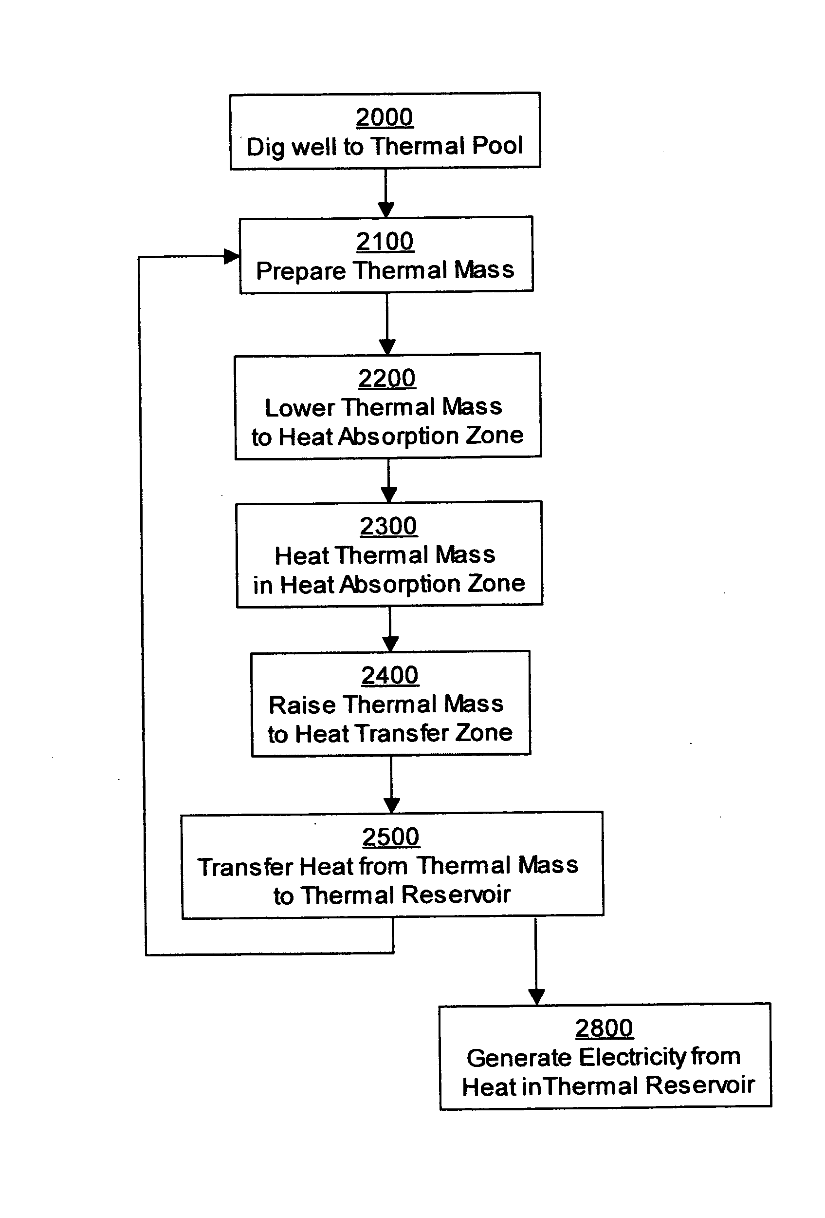
[0059]One embodiment of the invention is illustrated in more detail in FIG. 5 and FIG. 6. Note that these illustrations are not to scale, since the wells are anticipated to be kilometers deep while the thermal masses are expected to be, for example, 1 to 30 meters long and perhaps 50 to 100 centimeters in diameter.

[0060]In this embodiment of the invention, the deeper part of the well shaft 60 surrounded by the thermal pool 560, can be lined with a thermal casing 64 that facilitates the transfer of heat from the thermal pool 560 to the thermal mass 100. This thermal casing can be made using a material such as a thermally conducting grout, often made from compositions comprising water, cement, siliceous gel, and sometimes bentonite. Additional materials such as iron filings or other metallic powders can be mixed into the grout to enhance thermal conductivity. The surface can also be treated to be smooth to increase emissivity for enhancing radiative heat transfer. Althoug...

second embodiment

the Invention

[0084]FIG. 11, FIG. 12 and FIG. 13 show an alternative embodiment of the invention. In this embodiment, as in the first embodiment, a well shaft 60 can be dug to a thermal pool 560. As before, the well shaft 60 can be lined with various casings, such as an insulating casing 62 in the upper portions of the shaft and a thermal casing 64 in the lower portion of the shaft. As before, a thermal mass 100-2 is lowered on a suspension cable 140 to a Heat Absorption Zone, heated by the thermal pool 560. After heating, the thermal mass 100-2 is then raised to a Heat transfer Zone near the surface of the Earth 10, and the heat unloaded into a thermal reservoir 300 contained in a thermal reservoir containment 380. The thermal mass 100-2 again comprises a cylindrical exterior shell 101, which can be the same design as was illustrated for the previous embodiment in FIG. 8, and can also have an interior cavity containing a thermal fluid 55 covered with a cover gas 56.

[0085]However, in...

third embodiment

the Invention

[0094]In the previously described embodiments, the thermal mass can be lowered into the thermal well and then raised once it has acquired heat. However, for a single thermal mass raised into a single thermal well, significant energy must be expended to raise the thermal mass against the pull of gravity. This may place a practical limit on the mass that can be used, since a thermal mass that is heavier will require more energy to raise, especially when the wells are at depths of kilometers. However, heavier masses may be advantageous from a thermal energy point of view, in that heavier, denser thermal masses can have a significantly larger heat capacity, and therefore acquire more heat to be harvested once the thermal mass is returned to the surface.

[0095]An alternative embodiment of the invention can mitigate the energy expenditure required to raise warmed thermal masses from the thermal well. In this embodiment, at least two (2) paired thermal masses are connected by a...


PUM


Abstract

This invention provides a method of extracting geothermal energy, generally comprising the steps of: insertion of a thermal mass into a Heat Absorption Zone, absorbing heat in thermal mass, raising the thermal mass to a Heat Transfer Zone, and transferring the heat from the thermal mass. The acquired heat can be used to generate electricity or to drive an industrial process.
The thermal mass can have internal chambers containing a liquid such as molten salt, and can also have structures facilitating heat exchange using a thermal exchange fluid, such as a gas or a glycol-based fluid.
In some embodiments, two thermal masses are used as counterweights, reducing the energy consumed in bringing the heat in the thermal masses to the surface. In other embodiments, solid or molten salt can be directly supplied to a well shaft to acquire geothermal heat and returned to the surface in a closed loop system.

Description

CROSS-REFERENCE TO RELATED APPLICATIONS[0001]This patent application claims the benefit of U.S. Provisional Patent Application No. 61 / 633,756, filed on Feb. 17, 2012, the contents of which are also incorporated herein by reference.FIELD OF THE INVENTION[0002]This invention relates to the field of geothermal energy extraction, and more specifically to the process of extracting heat from wells drilled into the Earth and using the extracted heat for an industrial process, such as the generation of electricity, or to drive a chemical or other manufacturing process.BACKGROUND OF THE INVENTION[0003]Mankind has used geothermal energy for millennia. It is known that human tribes of the Neolithic Age bathed in natural hot springs, and the ancient Chinese and Roman civilizations built facilities to harness geothermal pools. With the core of the Earth believed to be over 5,000° C., it has been estimated that there is enough heat stored from the original formation of the Earth and generated by ...

Claims


Application Information

Patent Timeline
IPC IPC(8): F03G7/04F28D15/00
CPCF03G7/04F28D15/00Y02E10/10F28D2020/0047Y02E60/142F24J3/08F28D20/0034Y02E70/30Y02E10/46F24T10/10F24T10/30Y02E60/14Y02P80/20
Inventor MCBAY, DAVID ALAN
Owner DAVID ALAN MCBAY
Why Eureka
Try Eureka