
Light Source Device with Outer Lens and Light Source System Using the Same

a technology of light source device and light source system, which is applied in the direction of semiconductor devices, lighting and heating devices, instruments, etc., can solve problems such as heat dissipation, and achieve the effect of high smoothness

Active Publication Date: 2013-09-05
DARWIN PRECISIONS CORP
View PDF31 Cites 23 Cited by
  • Summary
  • Abstract
  • Description
  • Claims
  • Application Information

AI Technical Summary

Benefits of technology

The present invention provides a light source device and a light source system that emit light with higher smoothness and favorable heat dissipation properties. The light source is placed below the opening of a hole, and its illumination area is directed towards the hole. The opening of the hole covers the projection area of the illumination area onto the bottom surface, allowing the light emitted from the illumination area to pass through the inner top surface and be emitted out to the projection area corresponding to the light-emitting top surface. This design improves light smoothness by decreasing the chances of total reflection and prevents the center from generating dark spots and rings of strong light forming outside the dark spot.

Problems solved by technology

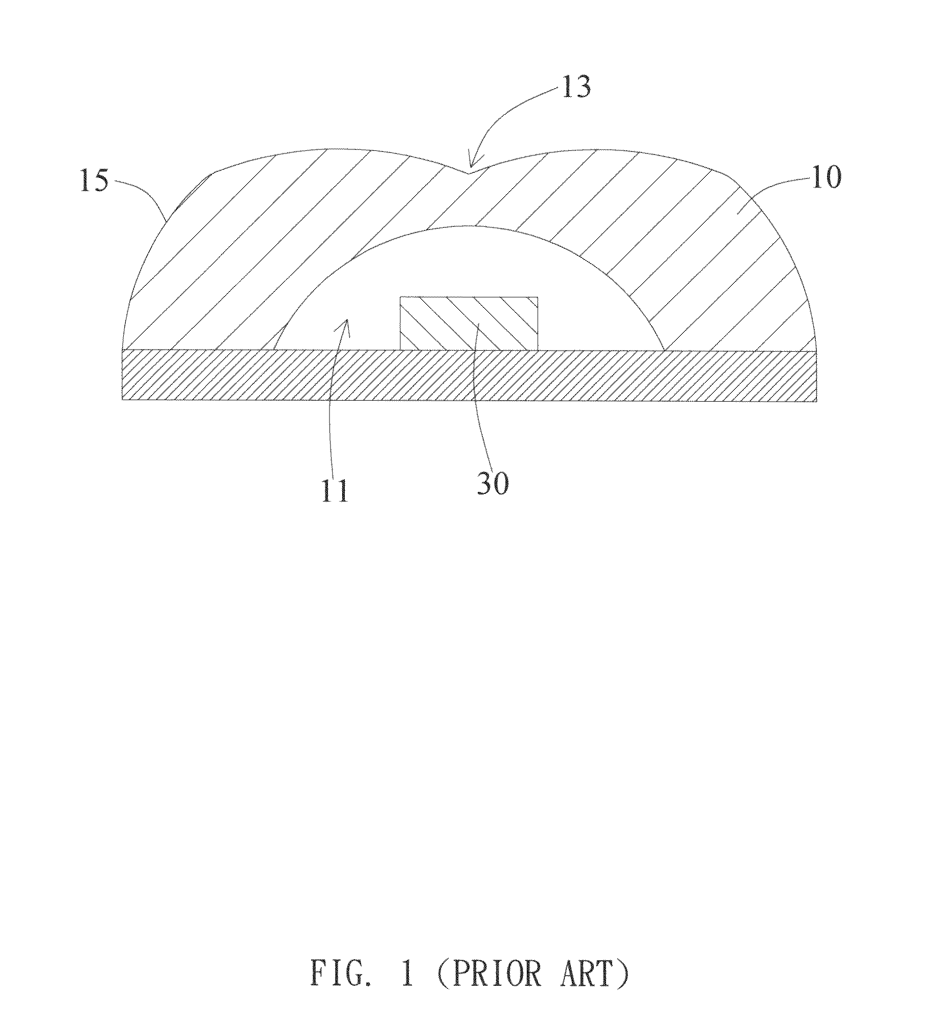
However, the distribution of light produced by the above design will typically form ring shaped areas of strong light.
In addition, since the light-emitting diode chip 30 is completely covered within the cavity 11, there will be heat dissipation problems.

Method used


Image

  • Light Source Device with Outer Lens and Light Source System Using the Same
  • Light Source Device with Outer Lens and Light Source System Using the Same
  • Light Source Device with Outer Lens and Light Source System Using the Same

Examples


Embodiment Construction

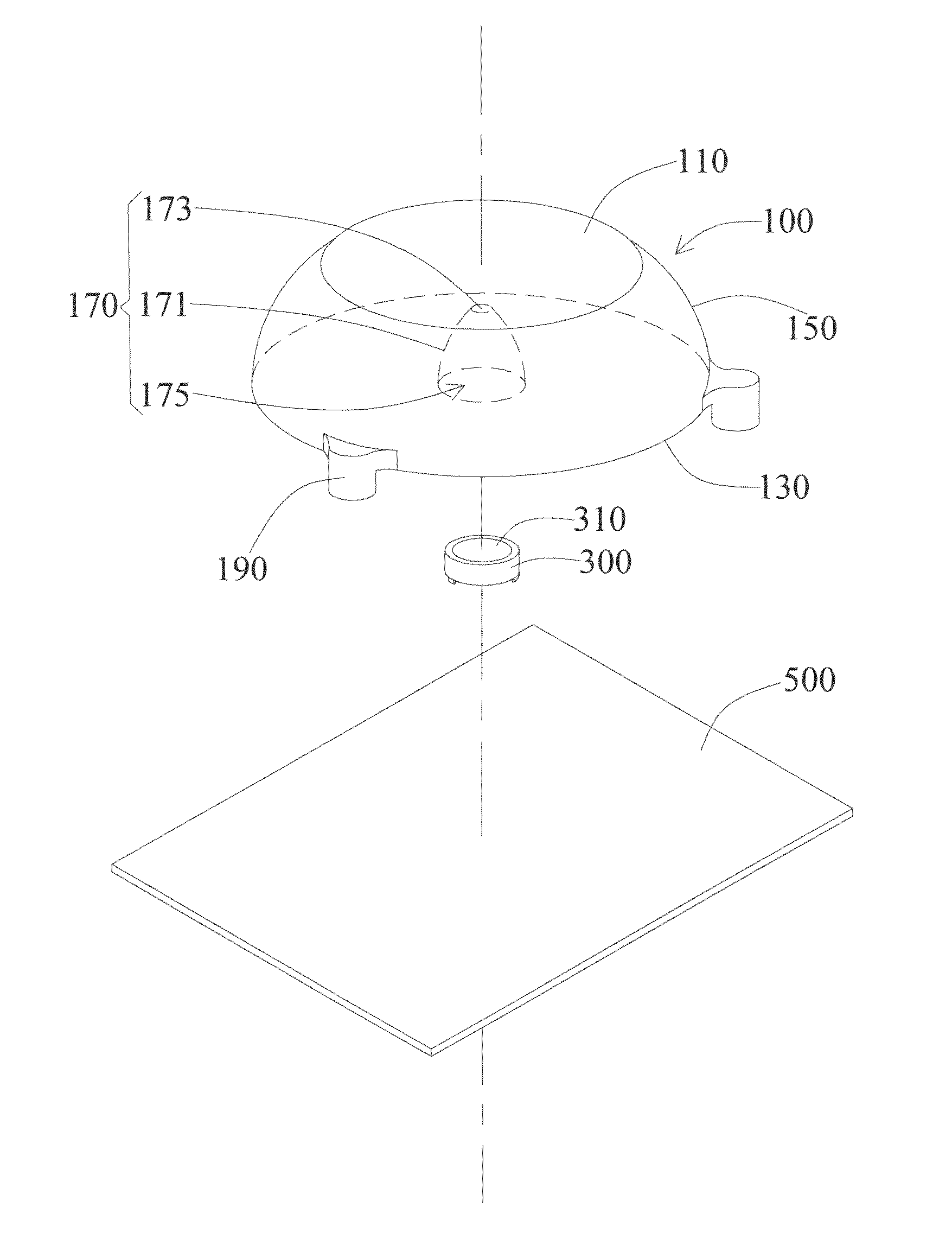
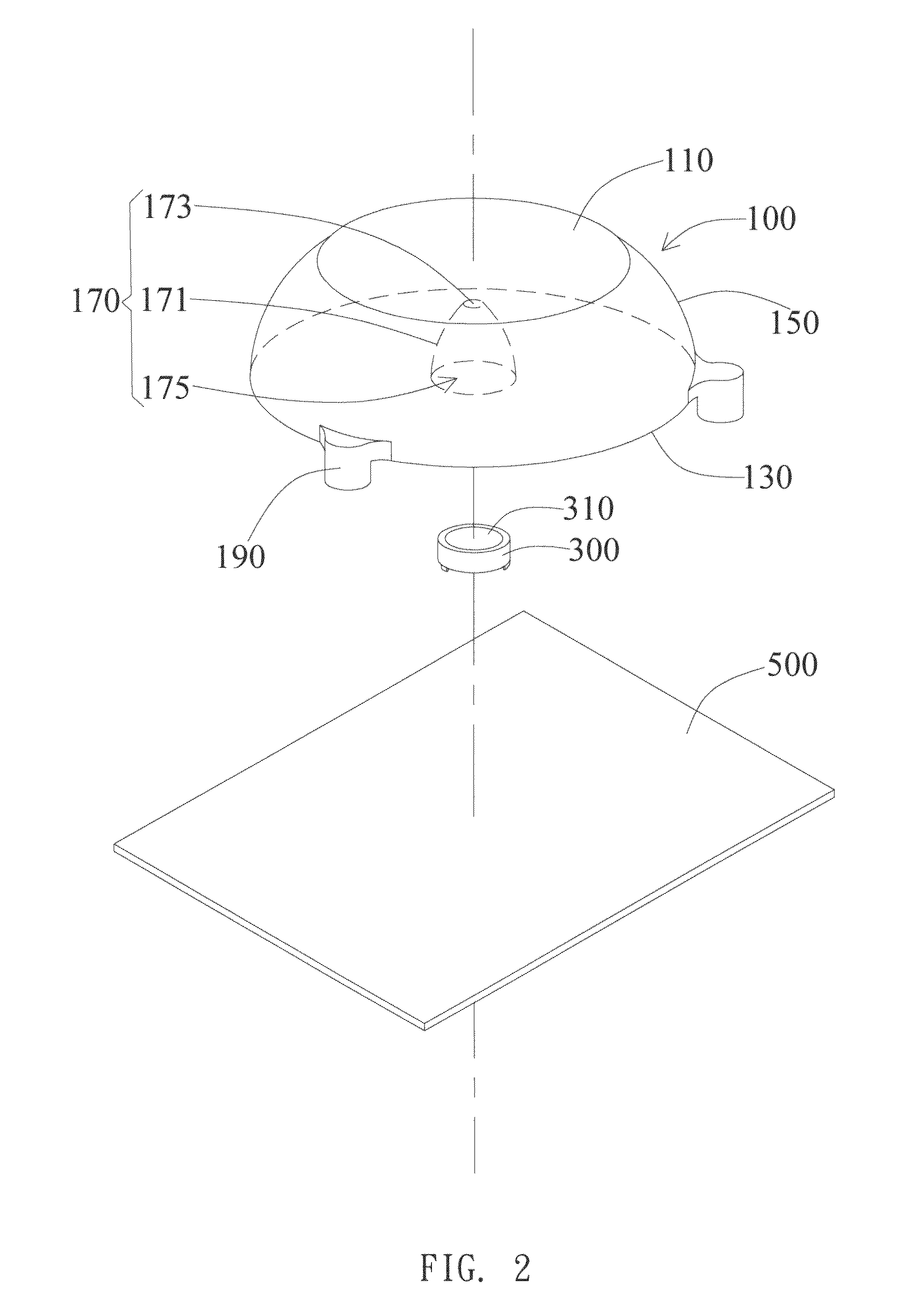
[0027]The present invention provides a light source device. In a preferred embodiment, the light source device is a light-emitting diode (LED) light source device. However, in other different embodiments, the light source device may also utilize other light sources that have an illumination area. In addition, the present invention provides a light source system that includes a plurality of the light source devices. Through adjusting the arrangement and direction of the light source devices, better light effects may be produced.

[0028]As shown in FIGS. 2 and 3, the light source device includes a lens 100 and a light source 300. The lens 100 has a light-emitting top surface 110, a bottom surface 130 opposite to the light-emitting top surface 110, and an outer wall surface 150 extending and connecting from the bottom surface 130 to the light-emitting top surface 110. In the present embodiment, the light-emitting top surface 110 and the bottom surface 130 are in the shape of a circle. Ho...


PUM


Abstract

A light source device and a light source system using the same are provided. The light source device includes a lens and a light source disposed under the lens. The lens has a light-emitting top surface and a bottom surface having a hole that is surrounded by an inner wall surface and an inner top surface. The inner top surface and a projection area of thereof onto the light-emitting top surface are flat surfaces. The light source has an illumination area, wherein an opening of the hole covers a projection area of the illumination area onto the bottom surface. The light source system includes a plurality of the light source device disposed in a honeycomb arrangement, wherein the light source devices are spaced apart from each other.

Description

BACKGROUND OF THE INVENTION[0001]1. Field of the Invention[0002]The present invention generally relates to a light source device and a light source system formed thereof; particularly, the present invention relates to a light source device and a light source system formed thereof that has an external lens.[0003]2. Description of the Related Art[0004]Within various technical fields, especially to the field of display technology and illumination equipments, the design of light sources has always been an important aspect of light sources. Conventional light sources typically utilize light bulbs or incandescent tubes as light sources. As the technology of light-emitting diodes (LED) has matured and since LEDs have advantages of being small and being environmentally friendly by saving energy, LEDs have gradually become a mainstay on the market.[0005]In order to increase the illumination area in practical usage, the conventional light source as shown in FIG. 1 has a lens 10 disposed and c...

Claims


Application Information

Patent Timeline
IPC IPC(8): F21V5/04
CPCF21V5/04F21V17/005G02B19/0061G02B19/0014F21Y2101/02F21Y2115/10
Inventor WANG, CHUN-LINSHEN, YU-SHANCHANG, CHUNG-HSING
Owner DARWIN PRECISIONS CORP
Learn More