
Magnetic resonance imaging and radiotherapy apparatus with at least two-transmit-and receive channels

Active Publication Date: 2013-08-29
KONINKLIJKE PHILIPS ELECTRONICS NV
View PDF18 Cites 31 Cited by
  • Summary
  • Abstract
  • Description
  • Claims
  • Application Information

AI Technical Summary

Benefits of technology

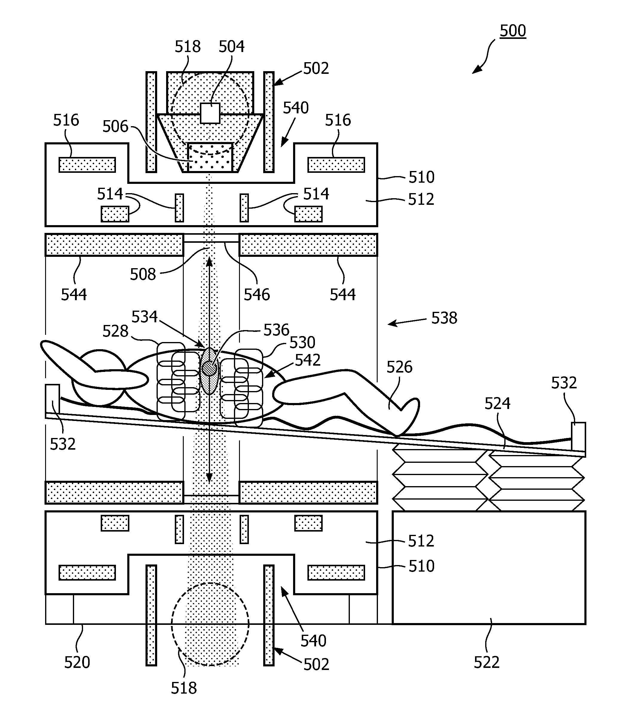
The invention solves the problem of limited placement of a target zone during magnetic resonance imaging and radiotherapy treatment by using a cylindrical superconducting magnet with a recess for positioning the radiotherapy source closer to the subject. This eliminates the need for a volume body coil and reduces the cost of the therapeutic apparatus.

Problems solved by technology

A difficulty encountered in guiding radiotherapy treatments using magnetic resonance (MR) imaging is the limited space in magnets that are useful for clinical imaging, such as cylindrical superconducting magnets.
For such magnets there is simply is not sufficient space in a magnet to position the target zone along the rotational axis of the radiotherapy source.

Method used


Image

  • Magnetic resonance imaging and radiotherapy apparatus with at least two-transmit-and receive channels
  • Magnetic resonance imaging and radiotherapy apparatus with at least two-transmit-and receive channels
  • Magnetic resonance imaging and radiotherapy apparatus with at least two-transmit-and receive channels

Examples


Embodiment Construction

[0064]Like numbered elements in these figures are either equivalent elements or perform the same function. Elements which have been discussed previously will not necessarily be discussed in later figures if the function is equivalent.

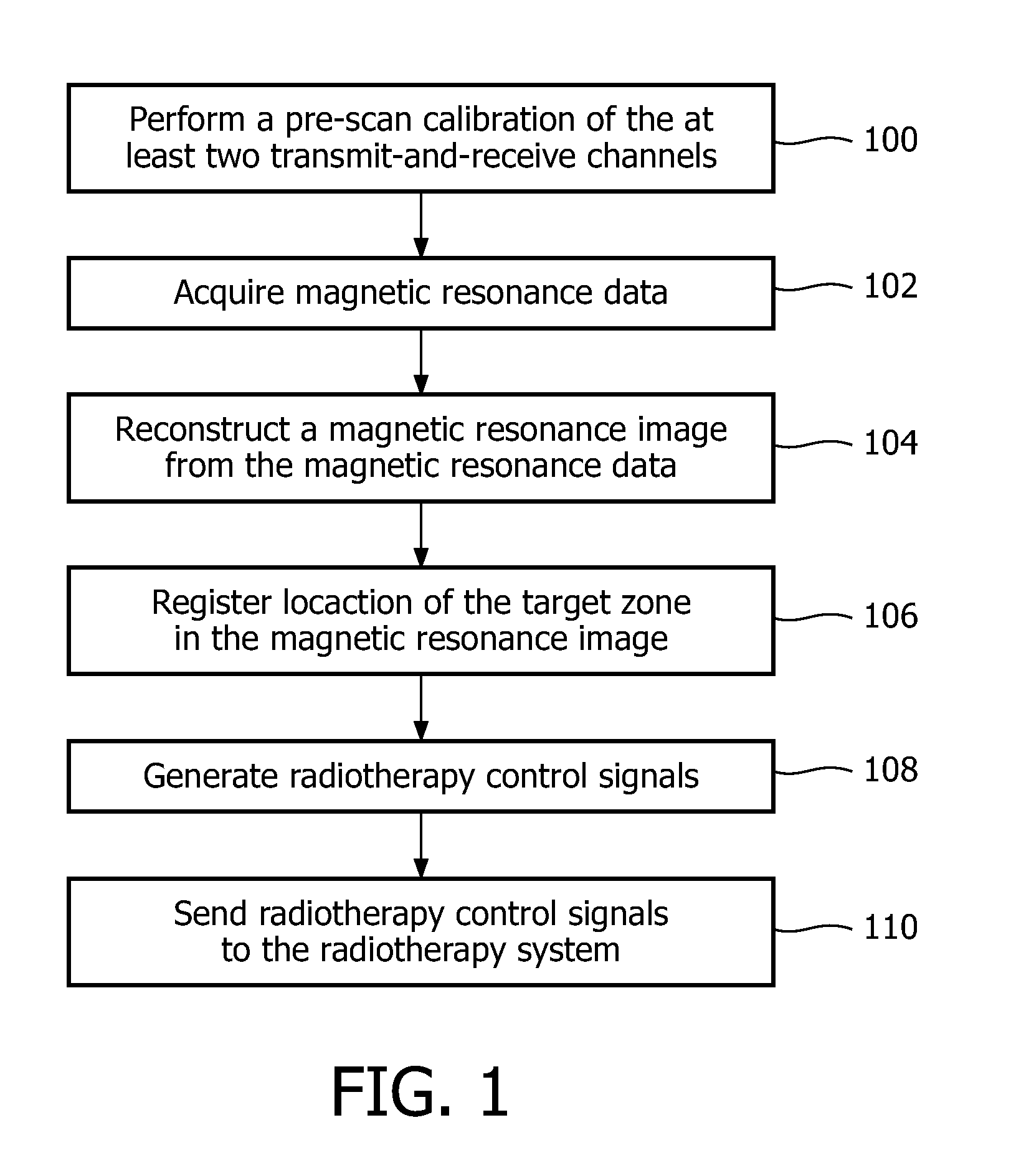
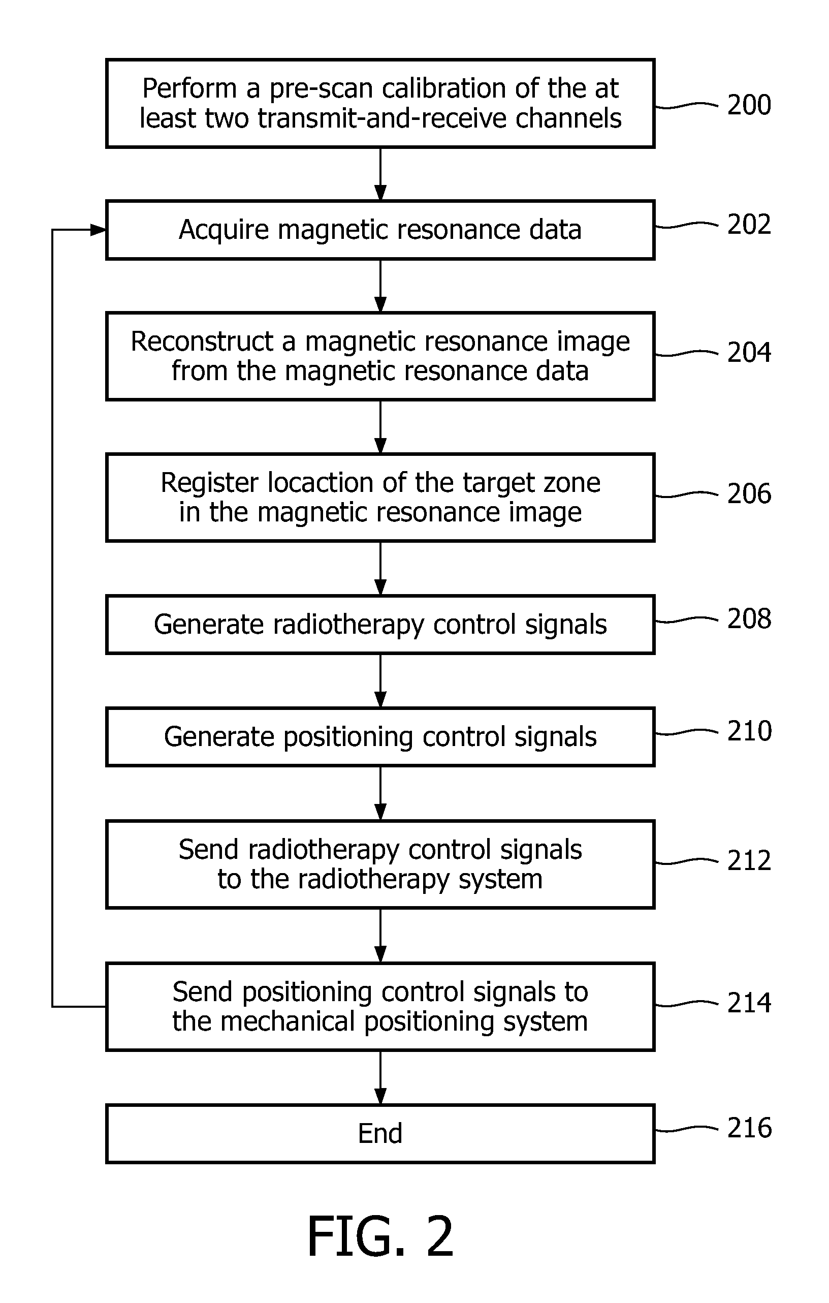
[0065]FIG. 1 shows a full flow diagram which illustrates an embodiment of a method according to the invention. In step 100 a pre-scan calibration of the at least two transmit-and-receive channels is performed. In step 102 magnetic resonance data is acquired. The magnetic resonance data is acquired using a calibration that was determined in step 100. Next in step 104 a magnetic resonance image is reconstructed from the magnetic resonance data. The magnetic resonance image may be one or a collection of magnetic resonance images. In step 106 the location of the target zone is registered in the magnetic resonance image. In step 108 radiotherapy control signals are generated. In step 110 the radiotherapy control signals are sent to the radiotherapy system. S...


PUM


Abstract

A therapeutic apparatus (500, 600) comprising a radiotherapy apparatus (502) for treating a target zone (318, 536) and a magnetic resonance imaging system (510, 532, 44, 602) for acquiring magnetic resonance imaging data (624). The radiotherapy apparatus comprises a radiotherapy source (300, 302, 304, 504) for directing electromagnetic radiation (310, 312, 314, 508) into the target zone. The radiotherapy apparatus is adapted for rotating the radiotherapy source at least partially around the magnetic resonance magnet. The magnetic resonance imaging system further comprises a radio-frequency transceiver (532) adapted for simultaneously acquiring the magnetic resonance data from at least two transmit-and-receive channels (528, 530). The therapeutic apparatus further comprises a processor (614) and a memory (620) containing machine executable instructions (636, 638, 640, 642, 644) for the processor. Execution of the instructions causes the processor to: calibrate (100, 200) the transmit-and-receive channels; acquire (102, 202) the magnetic resonance data; reconstruct (104, 204) a magnetic resonance image (626); register (106, 206) a location (628) of the target zone in the image; and generate (108, 208) radiotherapy control signals (630) using the registered image.

Description

TECHNICAL FIELD[0001]The invention relates to apparatuses for treating a target zone of a subject with radiotherapy, in particular the invention relates to radiotherapy apparatuses guided by magnetic resonance imaging.BACKGROUND OF THE INVENTION[0002]In routine practice of Radiotherapy (RT), the subject is positioned relative to the stationary center of the rotating arc carrying the RT source. Positioning implies both height and lateral adjustment of the subject table. This positioning is required to optimize the dose in the lesion beyond variation that can be obtained by applying RT rays from different angles.[0003]Integration of MR and Linear Accelerators (LINAC) opens new horizons in Radiotherapy by improved lesion targeting, especially for moving organs. In a practical implementation proposal, the LINAC rotates around the subject to hit the gross target volume (GTV) and clinical target volume (CTV) from multiple angles while minimizing the radiation exposure for surrounding tiss...

Claims


Application Information

Patent Timeline
IPC IPC(8): A61B5/055
CPCA61B5/0037A61B5/055A61B5/0555A61N5/1049A61N5/1065G01R33/4812A61N2005/1055A61N2005/1056G01R33/3806G01R33/4808A61N5/1069A61B5/70A61B6/00
Inventor HARVEY, PAUL ROYSTON
Owner KONINKLIJKE PHILIPS ELECTRONICS NV
Learn More