
Method and apparatus for high velocity ripple suppression of brushless DC motors having limited drive/amplifier bandwidth

a brushless dc motor and limited drive/amplifier technology, applied in the direction of motor/generator/converter stopper, dynamo-electric converter control, program control, etc., can solve the problem of bandwidth motor dynamics of the driver/amplifier that may not be able to respond sufficiently quickly, the effect of torque rippl

Inactive Publication Date: 2013-08-29
CANADIAN SPACE AGENCY
View PDF4 Cites 21 Cited by
  • Summary
  • Abstract
  • Description
  • Claims
  • Application Information

AI Technical Summary

Benefits of technology

The invention provides a method and device for reducing ripple in the torque of brushless DC motors at any given speed, regardless of the limitations of the driver / amplifier. The method involves calculating the Fourier coefficients of the current waveform based on the driver / amplifier's bandwidth and the rotor speed, to eliminate torque pulsations. The control signal, which is a periodic function, is approximated by a truncated Fourier series. When the motor speed changes, the coefficients are updated to generate an updated waveform that eliminates torque or velocity pulsations. The technical effect of this invention is to improve the smoothness and stability of brushless DC motors.

Problems solved by technology

However, in practice, the actual magneto-motive force generated by a non-ideal motor is not perfectly sinusoidally distributed, and can therefore result in ‘torque ripple’.
However, such motors tend to be expensive and bulky due to the construction and assembly of multiple coil windings.
However, at high rotor velocity the commutator generates high frequency control signals that the finite bandwidth motor dynamics of the driver / amplifier may not be able to respond sufficiently quickly.
Thus, complete compensation for the position nonlinearity of the motor torque cannot be achieved in the presence of amplifier dynamics, with the result that pulsation torque therefore appears at high motor velocities.
As discussed above, torque ripple can significantly deteriorate the performance of the servo control system and even lead to instability if the ripple frequency is close to the modal frequency of the closed-loop system.

Method used


Image

  • Method and apparatus for high velocity ripple suppression of brushless DC motors having limited drive/amplifier bandwidth
  • Method and apparatus for high velocity ripple suppression of brushless DC motors having limited drive/amplifier bandwidth
  • Method and apparatus for high velocity ripple suppression of brushless DC motors having limited drive/amplifier bandwidth

Examples


Embodiment Construction

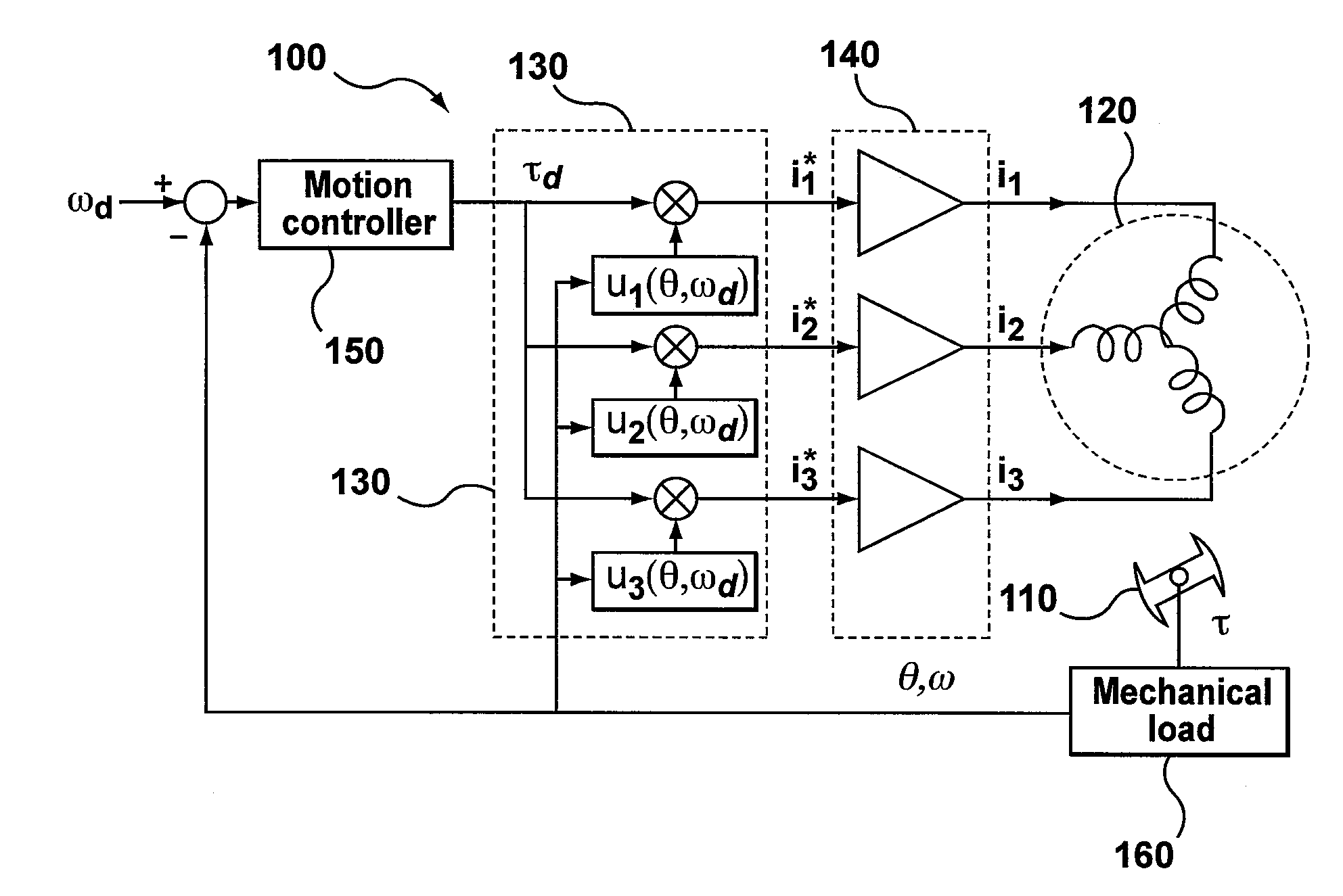
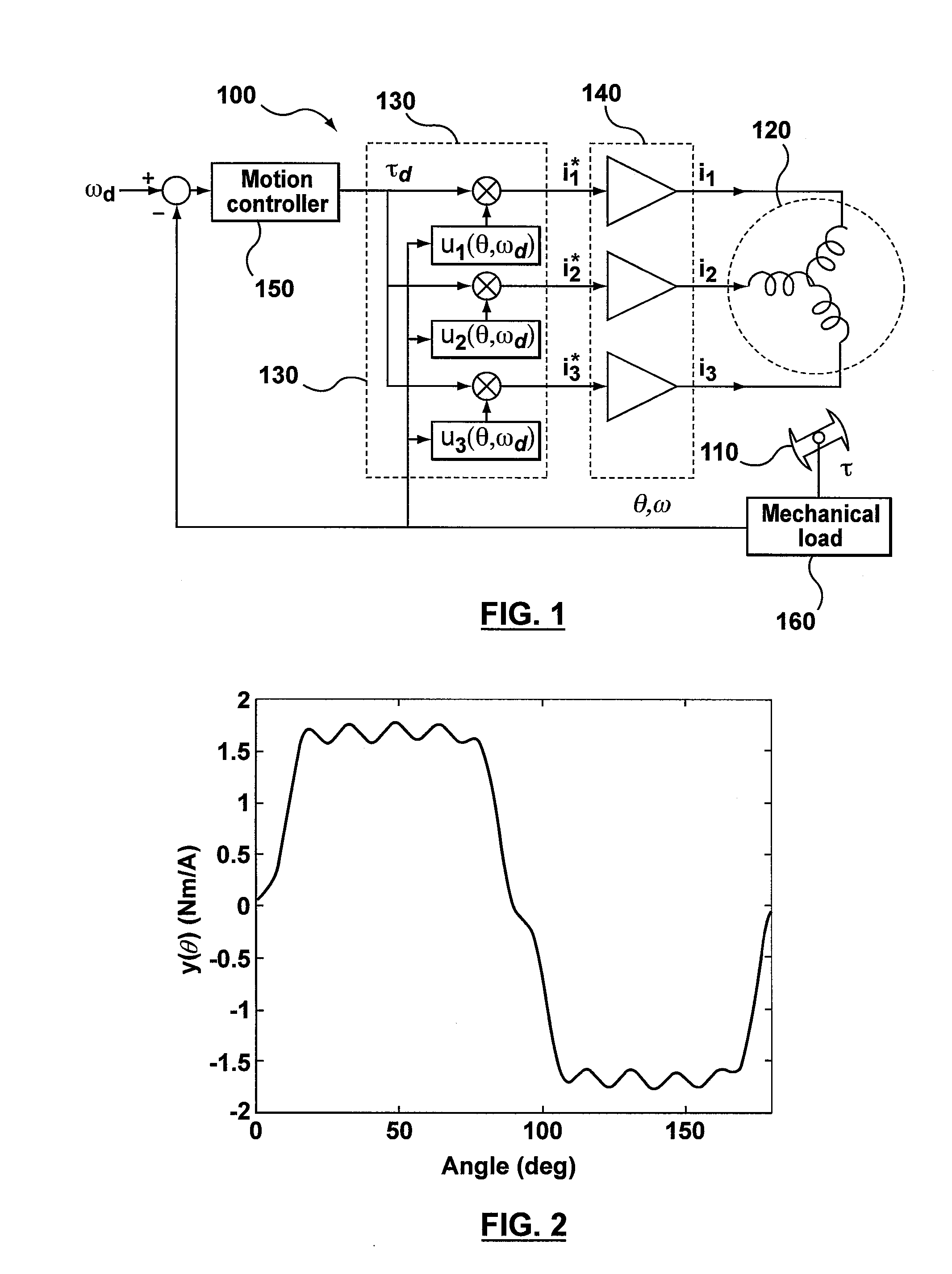
[0047]Turning to FIG. 1, a BLDC motor 100 is illustrated, comprising a rotor 110 having a plurality of permanent magnets (not shown) for driving a mechanical load 160, a stator 120 with electromagnetic coil armature windings, and a controller for controlling rotation of the rotor 110, including a commutator 130 for generating drive current (i*1, i*2, i*3) which is then amplified via driver / amplifier 140 (i1, i2, i3) and applied to the stator 120 in a specific order, and a motion controller 150 for pre-shaping the current waveform on the basis of an input signal representing a desired motor velocity ωd. The actual velocity w and rotor position angle θ are fed back from the mechanical load 160 driven by the rotor 110.

[0048]In order to better understand the scientific principles behind the invention, the theory relating to modeling and control of motor torque is discussed below in terms of Fourier series, followed by a discussion of how the commutation law is modified at high velocity ...


PUM


Abstract

A method and apparatus are provided for ripple suppression of brushless DC motors at any given velocity irrespective of the limited bandwidth of the driver / amplifier supplying the excitation currents to the stator. In a preferred embodiment, Fourier coefficients of the current waveform are calculated as a function of rotor velocity by taking into account the driver / amplifier's finite bandwidth dynamics. For a given velocity, Fourier coefficients of the series approximating the waveform (control signal) are calculated as a function of the rotor velocity and the amplifier dynamics, to generate a waveform that results in no torque or velocity pulsations. When changing the motor speed, the coefficients are updated (recalculated) based on the new desired velocity (and amplifier dynamics), resulting in generation of an updated waveform that results in no torque or velocity pulsations at the new motor speed.

Description

BACKGROUND OF THE INVENTION[0001]1. Field of the Invention[0002]The present invention is directed to brushless DC motors, and more particularly to a method and apparatus for ripple suppression in brushless DC motors having limited drive / amplifier bandwidth when operated at high velocity.[0003]2. Description of the Related Art[0004]Brushless DC (BLDC) motors, or electronically commutated motors (ECMs, EC motors) are electric motors that are powered by direct-current (DC) electricity via electronic commutation systems. BLDC motors exhibit linear current-to-torque and frequency-to-speed relationships and are commonly used as servo drives for precision motion control in numerous applications ranging from silicon wafer manufacturing, medical, robotics and automation industries to military applications.[0005]BLDC motors comprise a rotor having a plurality of permanent magnets, a stator with electromagnetic coil armature windings, and a commutator for continually switching the phase of the...

Claims


Application Information

Patent Timeline
Patent Type & Authority Applications(United States)
IPC IPC(8): H02P6/10
CPCH02P6/10H02P23/14G05B19/00
Inventor AGHILI, FARHAD
Owner CANADIAN SPACE AGENCY
Learn More