Combustion system for a gas turbine engine and method for directing fuel flow within the same

a combustion control system and gas turbine engine technology, applied in the direction of engine starters, turbine/propulsion engine ignition, machines/engines, etc., can solve the problems of less desirable, more expensive production and maintenance of dual-circuit nozzles, and unbalanced combustion and/or heat distribution in the combustor, so as to reduce the overall production cost of the engine, prevent hot-streaking substantially, and prevent unbalanced combustion and/or heat distribution.

Inactive Publication Date: 2013-08-29
HONEYWELL INT INC
View PDF4 Cites 5 Cited by
  • Summary
  • Abstract
  • Description
  • Claims
  • Application Information

AI Technical Summary

Benefits of technology

The patent describes a combustion system for a gas turbine engine that includes multiple fuel injector nozzles. The system includes a fuel flow directing system that selectively delivers fuel to each nozzle based on the engine's current operating condition. The system directs a preferential amount of fuel to the start nozzle during engine start-up, and an equalized amount of fuel to both the start and run nozzles as the engine reaches an idle setting. This approach improves fuel efficiency and reduces emissions. The method can be used in conjunction with the combustor described in this patent to optimize fuel delivery for improved performance and efficiency.

Problems solved by technology

However, dual-circuit nozzles are more expensive to produce and maintain than single-circuit nozzles, and as such are less desirable.

Method used


Image

  • Combustion system for a gas turbine engine and method for directing fuel flow within the same
  • Combustion system for a gas turbine engine and method for directing fuel flow within the same
  • Combustion system for a gas turbine engine and method for directing fuel flow within the same

Examples


Embodiment Construction

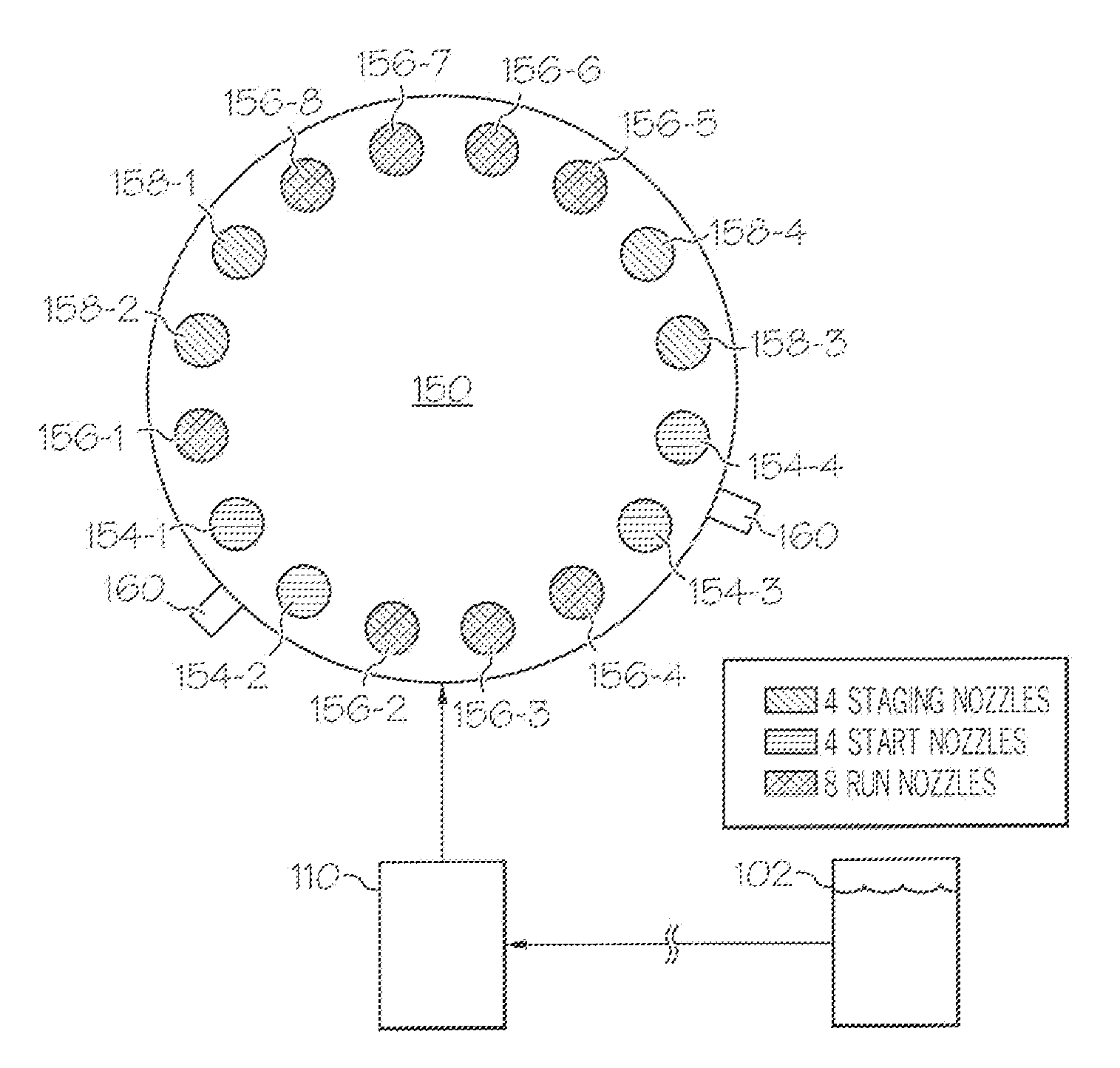
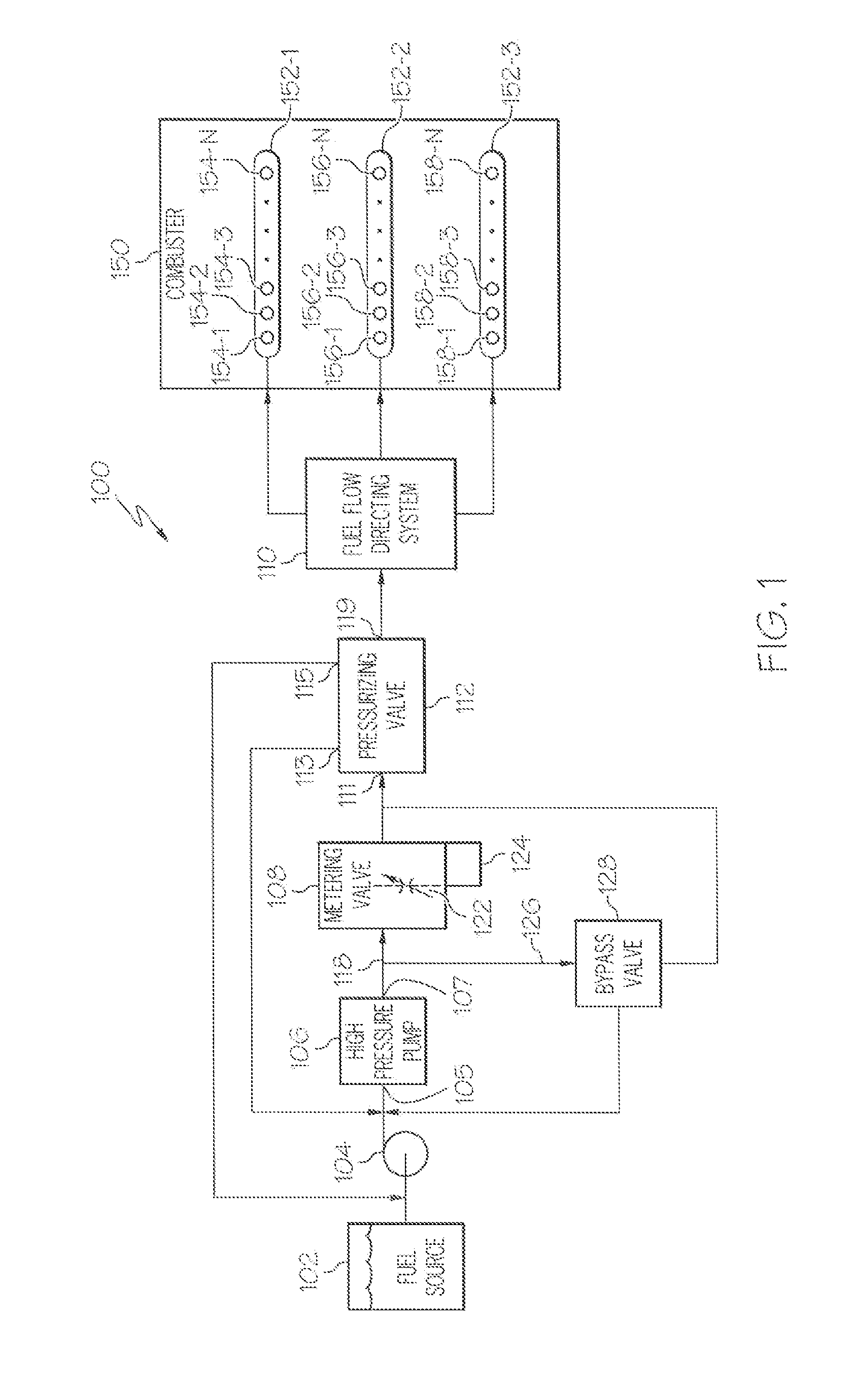
[0015]The following detailed description is merely exemplary in nature and is not intended to limit the invention or the application and uses of the invention. As used herein, the word “exemplary” means “serving as an example, instance, or illustration.” Thus, any embodiment described herein as “exemplary” is not necessarily to be construed as preferred or advantageous over other embodiments. All of the embodiments described herein are exemplary embodiments provided to enable persons skilled in the art to make or use the invention and not to limit the scope of the invention which is defined by the claims. Furthermore, there is no intention to be bound by any expressed or implied theory presented in the preceding technical field, background, brief summary, or the following detailed description.

[0016]FIG. 1 depicts a block diagram of an exemplary embodiment of a gas turbine engine fuel flow control system 100. The depicted system 100 includes a fuel source 102, one or more pumps 104, ...


PUM


Abstract

Disclosed is a combustion system for a gas turbine engine, which includes a combustor and a plurality of fuel injector nozzles within the combustor. The plurality of fuel injector nozzles include at least one start nozzle and at least of run nozzle, wherein each of the plurality of fuel injector nozzles is a single-circuit fuel injector nozzle. The combustion system further includes a fuel flow directing system to selectively deliver fuel flow to each of the at least one start nozzle and at least one run nozzle, wherein the fuel flow directing system is configured to deliver preferential flow of fuel to the at least one start nozzle during an engine start-up procedure and is further configured to deliver an equalized flow both of the at least one start nozzle and the at least one run nozzle as a total engine fuel flow is near or above an idle setting.

Description

TECHNICAL FIELD[0001]The present invention generally relates to gas turbine engine fuel combustion and combustion control systems, and more particularly relates to a combustor for a gas turbine engine and methods for directing fuel flow within the combustor.BACKGROUND[0002]The starting of a gas turbine engine is a complex process and generally includes two stages. In the first stage, the gas turbine engine is rotated by a torque provided by an external source, for example, by a starter. When a predetermined compressor pressure or speed is reached, fuel flow is injected at a controlled rate into the combustor to mix with the air flow and the mixture is exposed to an ignition source and eventually ignition occurs. In the second stage the fuel flow is continuously injected into the combustor, enabling the local ignition to propagate and spread in order to form stable combustion in the combustor. Fuel flow during this stage must be high enough so as to ensure light-off of all fuel injec...

Claims


Application Information

Patent Timeline
IPC IPC(8): F02C7/228F02C7/26
CPCF02C7/22F02C9/26F02C7/26
Inventor DUDEBOUT, RODOLPHEBOHMAN, RICHARDSTRIKER, DONMCPHERSON, MICHAELGREENMAN, MATT
Owner HONEYWELL INT INC
Why Eureka
Try Eureka