
Measuring device, measuring method, and tomographic apparatus

a technology of measuring device and tomographic apparatus, which is applied in the field of measuring device and measuring method, and tomographic apparatus, can solve the problems of difficulty in having sufficient measurement time length, coarse resolution, and the inability to accurately measure and achieve the effect of increasing the accuracy of measuring the physical property of an obj

Inactive Publication Date: 2013-08-22
CANON KK
View PDF4 Cites 9 Cited by
  • Summary
  • Abstract
  • Description
  • Claims
  • Application Information

AI Technical Summary

Benefits of technology

The present invention provides a measuring device and method for accurately measuring physical properties of an object, even when there are multiple interfaces that reflect electromagnetic waves. The device includes a detecting unit, an optical delaying unit, a collecting unit, a position adjusting unit, a waveform obtaining unit, a measured waveform forming unit, and a tomographic apparatus. The method involves adjusting the position of the object and detecting the electromagnetic wave pulse using the detecting unit. The optical delaying unit delays the optical path length of the excitation light and the collected electromagnetic wave pulses are collected at a collection point. The position adjusting unit adjusts the position of the object to focus the electromagnetic wave pulse on at least one of the first and second reflection portions of the object. The waveform obtaining unit changes the optical path length and obtains a time waveform from the detected electromagnetic wave. The measured waveform is formed by combining the first and second obtained waveforms. The tomographic apparatus includes a stage that holds the object and a stage relatively moving with the object and the position of the electromagnetic wave pulse. The invention allows for accurate and precise measurement of physical properties of objects, even when there are multiple interfaces that reflect electromagnetic waves.

Problems solved by technology

In the case where a reflected-pulse signal from a certain interface is extracted from a time waveform of a detected reflected pulse and a physical property is obtained, it is difficult to have sufficient measurement time length, resolution is coarse, and the accuracy of measurement of the physical property of an object may decrease.

Method used


Image

  • Measuring device, measuring method, and tomographic apparatus
  • Measuring device, measuring method, and tomographic apparatus
  • Measuring device, measuring method, and tomographic apparatus

Examples


first embodiment

[0029]A physical property measuring device according to a first embodiment is described below with reference to the drawings.

General Configuration of Physical Property Measuring Device

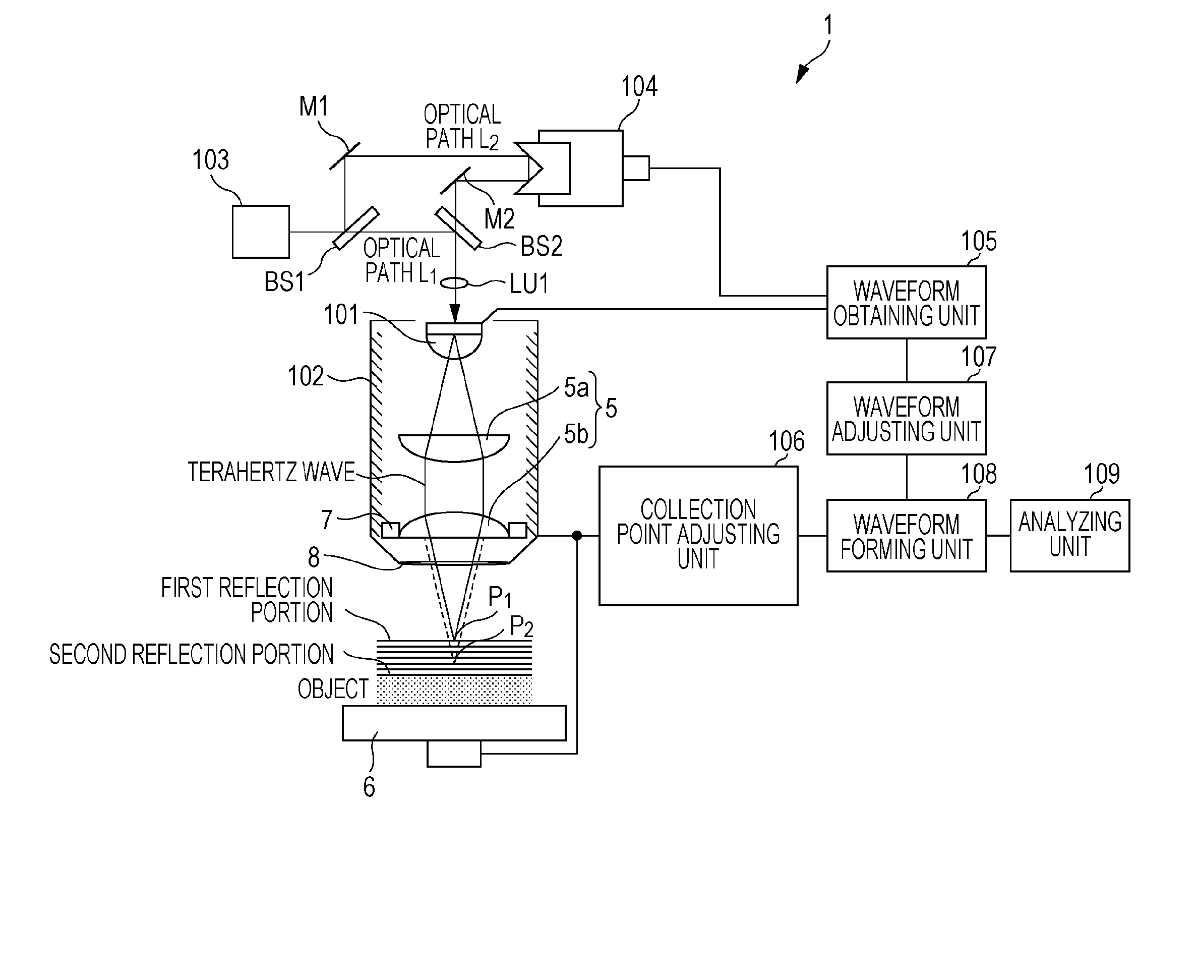
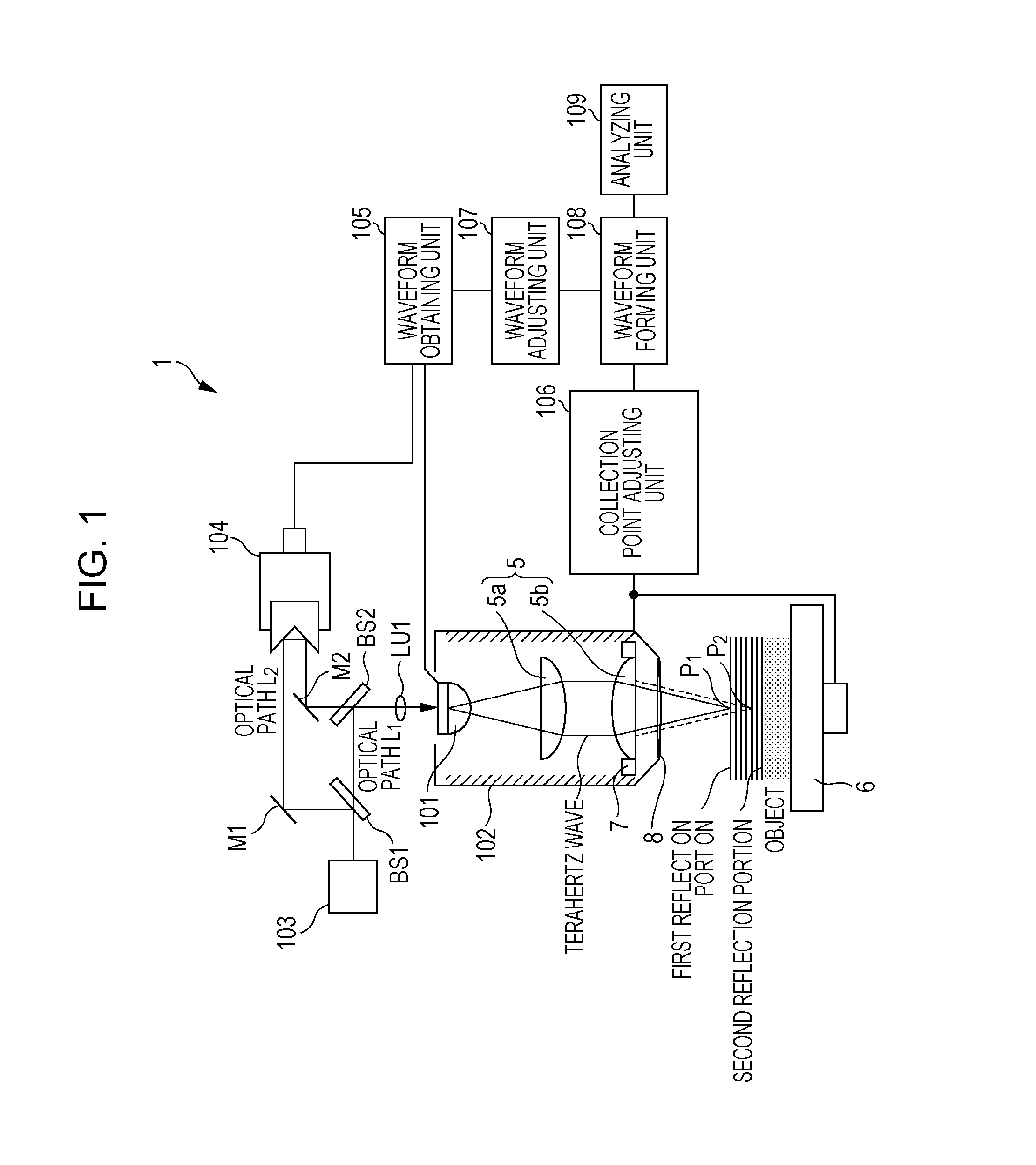
[0030]FIG. 1 illustrates a physical property measuring device 1 according to the present embodiment.

[0031]The physical property measuring device 1 includes a light source 103, a generating and detecting unit 101 that generates and detects an electromagnetic wave pulse, and a shaping unit 102 that collects and shapes an electromagnetic wave pulse and measures a physical property of an object. The light source 103 emits excitation light (laser light) for use in generating and detecting an electromagnetic wave pulse by the generating and detecting unit 101.

[0032]The physical property measuring device 1 further includes a waveform obtaining unit 105, a collection point adjusting unit 106, a waveform adjusting unit 107, a waveform forming unit 108, and an analyzing unit 109.

[0033]The waveform obtaining unit...

second embodiment

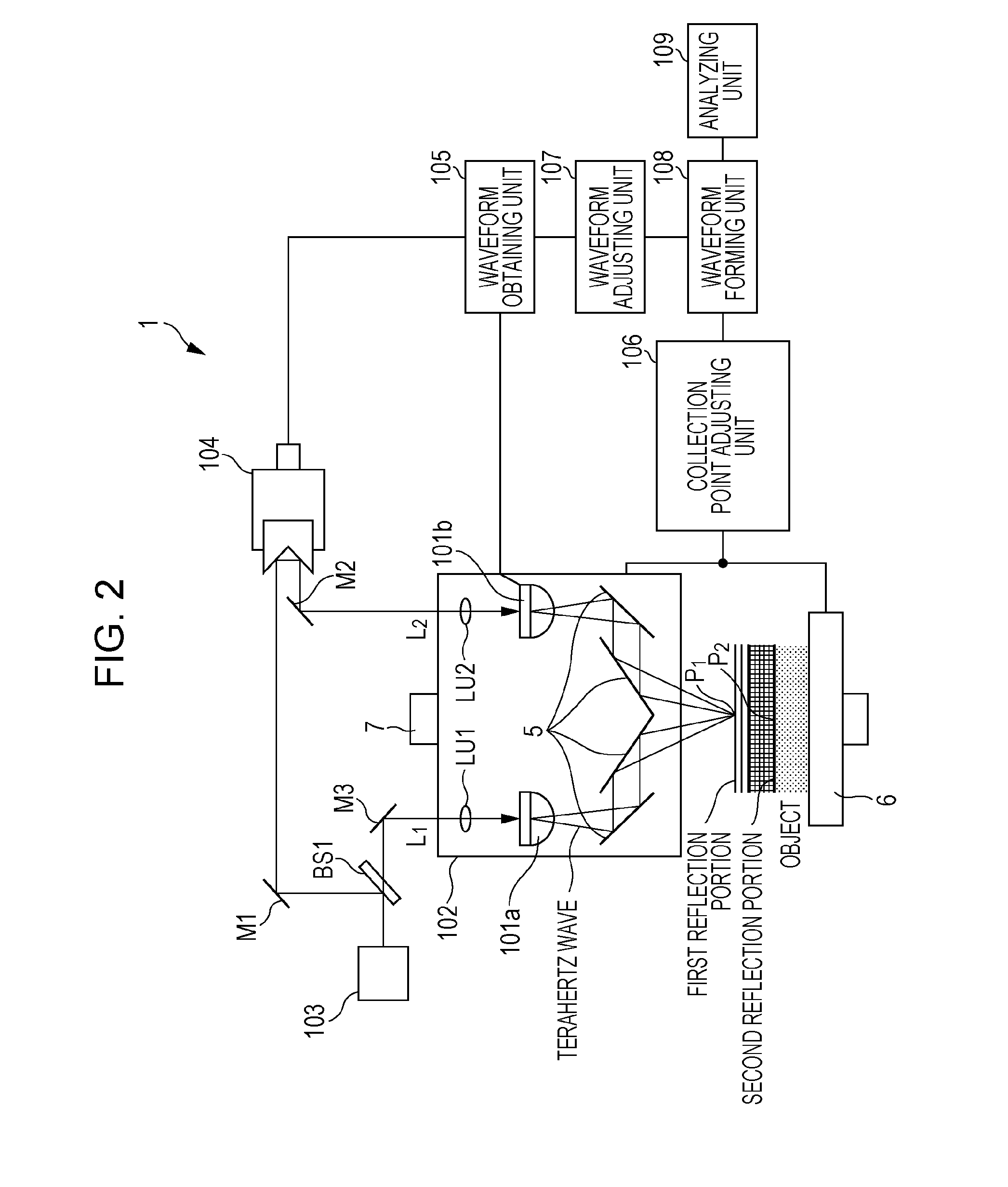
[0101]A second embodiment is distinctive in that a producing element and a detecting element for a terahertz wave are discrete and different from the first embodiment in the configuration of the portion generating and detecting a terahertz wave pulse. The second embodiment is described below with reference to FIG. 2. The description of the components common to the first embodiment is omitted.

[0102]FIG. 2 illustrates a physical property measuring apparatus according to the present embodiment.

[0103]In the present embodiment, the generating and detecting unit 101 includes two elements a generating element 101a and a detecting element 101b for respectively generating and detecting a terahertz wave. A plurality of mirrors is used as the collecting unit 5. Configuring the generating and detecting unit 101 with the generating element 101a and the detecting element 101b as separate devices can advantageously enhance the selection of a terahertz generating and detecting element. That is, dif...

third embodiment

[0105]A third embodiment is distinctive in that the physical property measuring device according to the first embodiment is applied to a tomographic apparatus and a stage that fixes an object is movable in parallel with the optical axis direction of a terahertz wave pulse. The third embodiment is described below with reference to the drawings. The description of the components common to the first embodiment is omitted.

[0106]FIG. 7 illustrates a tomographic apparatus according to the present embodiment.

[0107]The time axis of the time waveform of a terahertz wave pulse can be converted into a distance. Thus the time waveform of a terahertz wave pulse can be considered to be an A scan image in a tomographic image. A B scan image and three-dimensional tomographic image are obtainable by scanning the optical axis in which a terahertz wave pulse propagates along a direction perpendicular to the direction in which the terahertz wave pulse enters the object and performing measurement.

[0108]...


PUM


Abstract

A measuring device for measuring a physical property of an object which is irradiated with an electromagnetic wave pulse. The measuring device includes a waveform obtaining unit which obtains a time waveform from a signal relating to the electromagnetic wave pulse reflected from a first reflection portion and a second reflection portion of the object. The waveform obtaining unit obtains a first obtained waveform at a first collection point where a parallel region of the electromagnetic wave pulse is adjusted by a position adjusting unit so as to be in only one of the first reflection portion and the second reflection portion of the object, and obtains a second obtained waveform at a second collection point different from the first collection point. A waveform forming unit forms a measured waveform based on the first obtained waveform and the second obtained waveform.

Description

BACKGROUND OF THE INVENTION[0001]1. Field of the Invention[0002]The present invention relates to a measuring device, measuring method, and a tomographic apparatus for measuring a physical property using an electromagnetic wave.[0003]2. Description of the Related Art[0004]A characteristic absorption spectrum based on the structure and state of a substance, including a biomolecule, in a frequency band of a predetermined electromagnetic wave, can be typified by a terahertz wave. Terahertz waves are electromagnetic waves in a frequency band in a range from millimeter waves to terahertz waves, in particular, a frequency band from 0.03 THz to 30 THz.[0005]An inspection technique that makes use of such a characteristic absorption spectrum for analyzing or identifying a substance nondestructively using an electromagnetic wave of a predetermined frequency band of the terahertz domain has been developed. This inspection technique is expected to be applied to an imaging technique that substitu...

Claims


Application Information

Patent Timeline
IPC IPC(8): A61B5/00G01N21/35G01N21/3563G01N21/3586
CPCA61B5/0073A61B5/0507A61B5/7257
Inventor ITSUJI, TAKEAKI
Owner CANON KK
Learn More