
Toner, developer, and image forming apparatus

a technology of toner and developer, applied in the direction of electrographic process, electrographic apparatus, instruments, etc., can solve the problems of inability to obtain favorable image quality, large amount of wax exposed at the toner surface, and inability to yield adequate toner releasability, etc., to achieve excellent low temperature fixing ability, excellent resistance to smear, and transfer ability of toner

Inactive Publication Date: 2013-08-22
RICOH KK
View PDF9 Cites 16 Cited by
  • Summary
  • Abstract
  • Description
  • Claims
  • Application Information

AI Technical Summary

Benefits of technology

The present invention provides a toner with excellent resistance to smear, low temperature fixing ability, and transfer ability. It can be effectively cleaned in case of toner offset and form high quality images for a long period of time with minimal filming. The toner has the advantage of chemical toner with small particle size and excellent fluidity. Additionally, the invention provides a developer and an image forming apparatus which use the toner.

Problems solved by technology

On this occasion, when the dispersion diameter of the domain particles is too large, the proportion of the wax localized near the surfaces of toner particles relatively increases; thus, the domain particles may aggregate, causing degradation of particle fluidity, the wax or a carrier may transfer to a photoconductor, etc. during long-term use, causing filming, and so it may be impossible to obtain favorable image quality.
When the dispersion diameter of the domain particles is too small, the wax is finely dispersed to excess and thus adequate toner releasability may not be yielded.
In the kneading pulverization method, since it is difficult to control the dispersion diameter of the domain particles of the wax is liable to be present on fracture surfaces, the amount of the wax exposed at the toner surface is large and so the above problems such as degradation of particle fluidity and occurrence of filming may arise.
Further, there exist the following problems: the toner obtained by the kneading pulverization method generally has a broad particle size distribution, varies in frictional chargeability and easily causes fogging and the like; also, it is difficult to obtain a small-particle-diameter toner, i.e., a volume average particle diameter of 2 μm to 8 μm for reasons related to production efficiency, and the demand for improvement in image quality can hardly be met.
By the suspension polymerization method, it is difficult to make the wax appropriately present on the surfaces of the toner particles unless a dispersion stabilizer is used, because the wax tends to enter the oil droplets easily when the oil droplets are being formed; here, there is a problem in which if the dispersion stabilizer remains, it causes a decrease in chargeability.
Only spherical shaped toner particles are obtained, there is a problem of cleaning.
However, when the fine particles obtained after the solvent removal are aggregated, mere aggregation of the fine particles leads to insufficient cohesion thereof, causing cracks or the like at interfaces after the cohesion.
However, when the heating is carried out, blooming of a wax component finely dispersed in the toner particles may arise (the wax component may be deposited on the surfaces), the wax formed into spherical shape, and / or aggregation, etc. of finely dispersed particles of the wax may arise, thereby making it impossible to maintain the state in which the wax is finely dispersed in a sufficient manner.
Especially in the case where a wax (release agent) having a low melting point is used, it easily melts in the heating step, and thus there is a problem in which favorable toner releasability cannot be secured and so there is a lack of suitability of the toner for oilless toner fixation with a heat roller.
However, this method requires polymerization of a wax emulsion and a polymerizable vinyl monomer; moreover, the glass transition temperature Tg of a resin contained in the wax fine particles is high; thus, there is a problem in which the toner is inferior in low-temperature fixing ability and releasability at low temperatures.
However, the dispersion of the wax inside the toner particles is not analyzed and is therefore unknown.
However, analysis based upon ESCA can be performed only within approximately 0.1 μm in depth from the outermost surface of the toner, and thus it is difficult to know the dispersed state of the wax which lies further inside and suitably exhibits toner releasability in a fixing step.
On the other hand, when in a fixing device, a toner and the like adhere to and accumulate on a periphery of a fixing belt or fixing roller, fixing ability is degraded, and the toner, etc. further accumulates thereon, causing degradation of image quality.
As a result, a fixing unit is hard to be cleaned.
In these fields, when the toner obtained by the above-described method is used, image failure (granular smear) may occur, because an offset toner is not sufficiently cleaned with a cleaning member, adheres to a fixing belt, a fixing roller or a pressure roller, and then is transferred to a recording medium.
The cleaning ability of the offset toner, and the low temperature fixing ability and transfer ability of the toner are not satisfied simultaneously.
Therefore, it has been desired to provide a method for constantly, stably, efficiently producing a toner, which can form high quality images and has excellent resistance to smear with occurring less filming, while keeping advantages of the chemical toner having a small particle diameter and particle size distribution and excellent fluidity, but such a method has not yet been provided at the moment.

Method used


Image

  • Toner, developer, and image forming apparatus
  • Toner, developer, and image forming apparatus
  • Toner, developer, and image forming apparatus

Examples


example 1

Preparation of Organic Solvent Phase

[0308]A raw material solution was obtained by mixing 2,493 parts of Wax Dispersion Liquid 1, 500 parts of Masterbatch B and 1,012 parts of ethyl acetate for 1 hour.

[0309]Then, 1,324 parts of the raw material solution was moved into a reaction vessel. Subsequently, using a bead mill (ULTRA VISCOMILL, manufactured by AIMEX CO., Ltd.), the raw material solution was passed three times under the following conditions so as to disperse the carbon black and the wax: the liquid feed rate was 1 kg / hr, the disc circumferential velocity was 6 m / sec, and 0.5 mm-zirconia bead packed to 80% by volume. Subsequently, 1,324 parts of a 65% of ethyl acetate solution of Unmodified Polyester Resin A was added to the obtained dispersion liquid and passed through the bead mill once under the conditions described above, to thereby prepare an organic solvent phase.

[0310]The organic solvent phase had a solid content concentration of 50% under the measurement conditions of h...

example 2

[0323]Toner base particles were produced in the same manner as in Example 1, except that the heat temperature of the slurry after the removal of the surfactant was changed from 55° C. to 50° C. The toner base particles had a volume average particle diameter of 5.4 μm and a BET specific surface area of 2.4 m2 / g. Then, the toner base particles were treated with the external additive in the same manner as in Example 1, to thereby obtain a toner of Example 2.

example 3

[0324]Toner base particles were produced in the same manner as in Example 1, except that Unmodified Polyester Resin A was replaced with Unmodified Polyester Resin B in the preparation of the organic solvent phase. The toner base particles had a volume average particle diameter of 5.4 μm and a BET specific surface area of 2.3 m2 / g. Then, the toner base particles were treated with the external additive in the same manner as in Example 1, to thereby obtain a toner of Example 3.


PUM

PropertyMeasurementUnit
diameter D2aaaaaaaaaa
Tgaaaaaaaaaa

Abstract

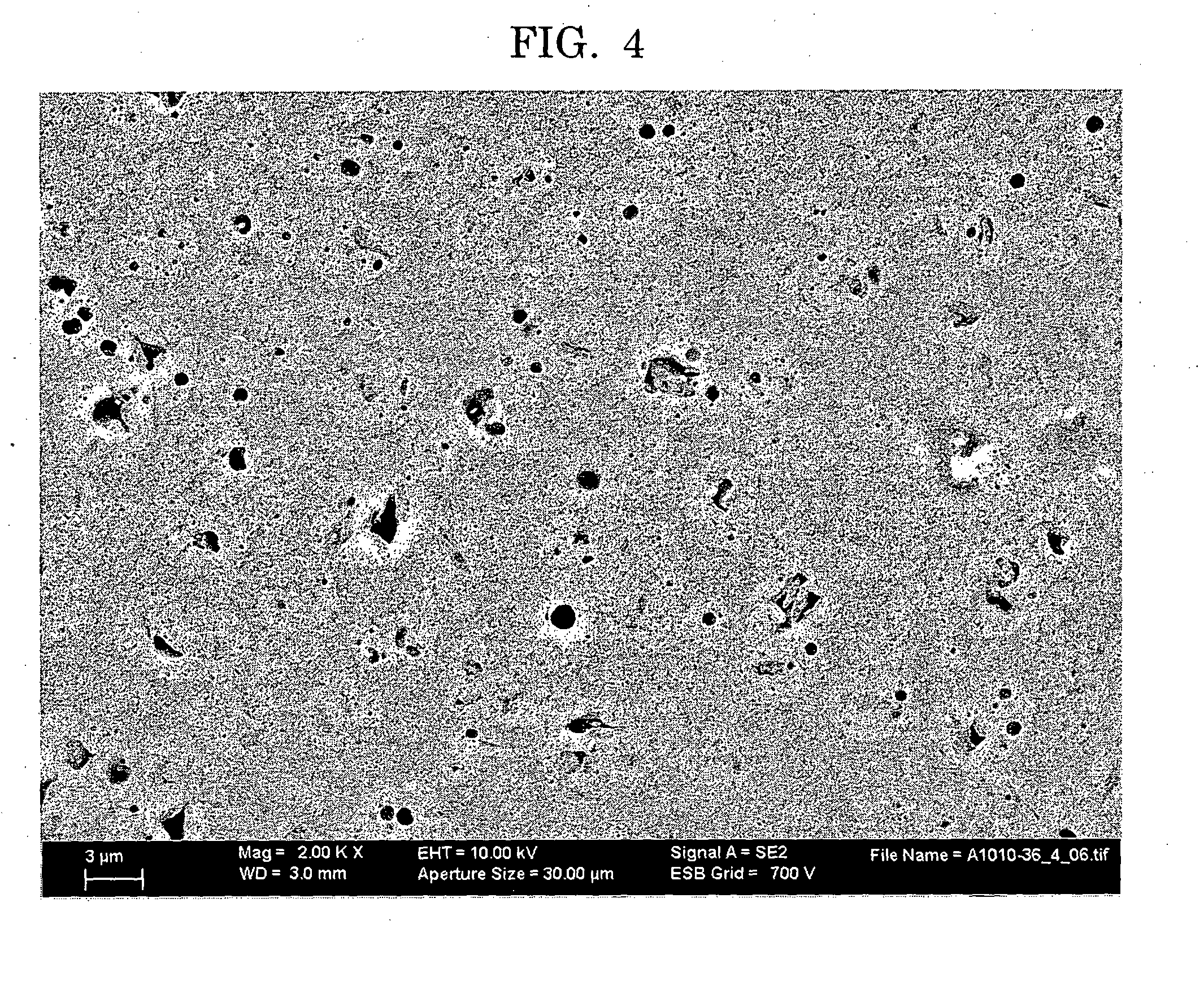
A toner contains a binder resin, a colorant, and a releasing agent, wherein the toner contains toner particles, and wherein a proportion of the toner particles containing one or more voids having diameters D1 of larger than 0.0 μm but 0.5 μm or smaller is more than 5.0% to 60%, and a proportion of the toner particles containing one or more voids having diameters D2 of 1.0 μm or larger is 10% or less.

Description

TECHNICAL FIELD[0001]The present invention relates to a toner, a developer and an image forming apparatus, suitably used for electrophotography, electrostatic recording, electrostatic printing, and the like.BACKGROUND ART[0002]Image formation by electrophotography is generally performed by a process which includes forming an electrostatic image on a photoconductor (electrostatic image bearing member), developing the electrostatic image with a developer so as to form a visible image (toner image), transferring the visible image onto a recording medium such as paper, and fixing the transferred visible image onto the recording medium with application of heat, pressure, a solvent gas, etc. so as to obtain a fixed image (see PTL 1).[0003]Regarding the developer, one-component developers for which magnetic toners or nonmagnetic toners are solely used, and two-component developers composed of toners and carriers are known. One-component developing methods are classified into magnetic one-c...

Claims


Application Information

Patent Timeline
Patent Type & Authority Applications(United States)
IPC IPC(8): G03G9/00G03G15/08
CPCG03G9/0819G03G9/0804G03G9/0806G03G9/08795G03G9/08755G03G9/08782G03G9/0827
Inventor SHIBA, MASANACHIBA, RYUTANAGATOMO, TSUNEYASU
Owner RICOH KK
Learn More