
High dynamic range & depth of field depth camera

a depth camera and dynamic range technology, applied in the field of high dynamic range and depth of field depth cameras, can solve the problems of difficult detection of sensor/camera objects further from the camera's light source, low reflectivity, and subject appearance that is “blown out” or very bright white, etc., to achieve the effect of increasing the dynamic range and depth of field

Active Publication Date: 2013-08-08
LUMENTUM OPERATIONS LLC
View PDF2 Cites 119 Cited by
  • Summary
  • Abstract
  • Description
  • Claims
  • Application Information

AI Technical Summary

Benefits of technology

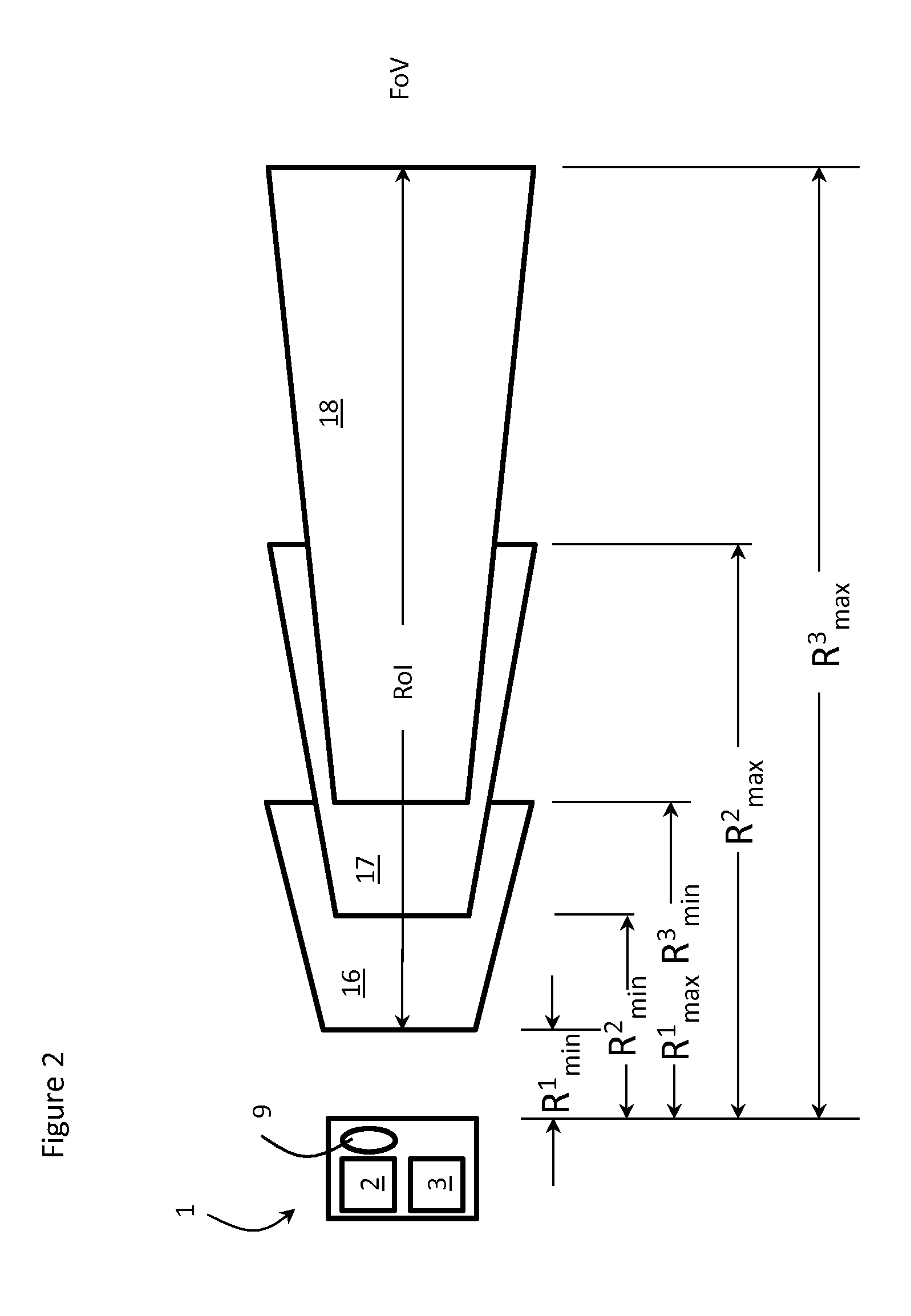
The present invention is related to a depth camera for a time of flight device that allows for the presentation of three-dimensional data to a host device. The depth camera comprises a light source with adjustable frequency and peak optical power, a detector array for receiving and detecting reflections off of objects, and a controller for adjusting the light source in a single frame time period to obtain multiple three-dimensional data measurements. The range of interest and field of view is divided into multiple volumes of interest with different integration time periods, peak optical power, and minimum and maximum distances from the light source to increase dynamic range and depth of field within each volume. The technical effect of the invention is to provide a more complete and accurate representation of the depth and dimensionality of objects within a given range of interest.

Problems solved by technology

Conversely, if you exposed the image for the background, your subject may appear “blown out” or very bright white and overexposed.
As with traditional photography cameras, depth of field, i.e. image sharpness consistency within the camera Field of View (FOV) and range of interest, and image dynamic range, i.e. image contrast range within the camera FOV and range of interest, requirements can be a significant challenge to a depth camera.
In the case of a depth camera, objects close to the camera's light source and or of high reflectivity can cause over saturation of sensor pixels while objects further from the camera's light source and or of low reflectivity can be difficult for the sensor / camera to detect at all.

Method used


Image

  • High dynamic range & depth of field depth camera
  • High dynamic range & depth of field depth camera
  • High dynamic range & depth of field depth camera

Examples


Embodiment Construction

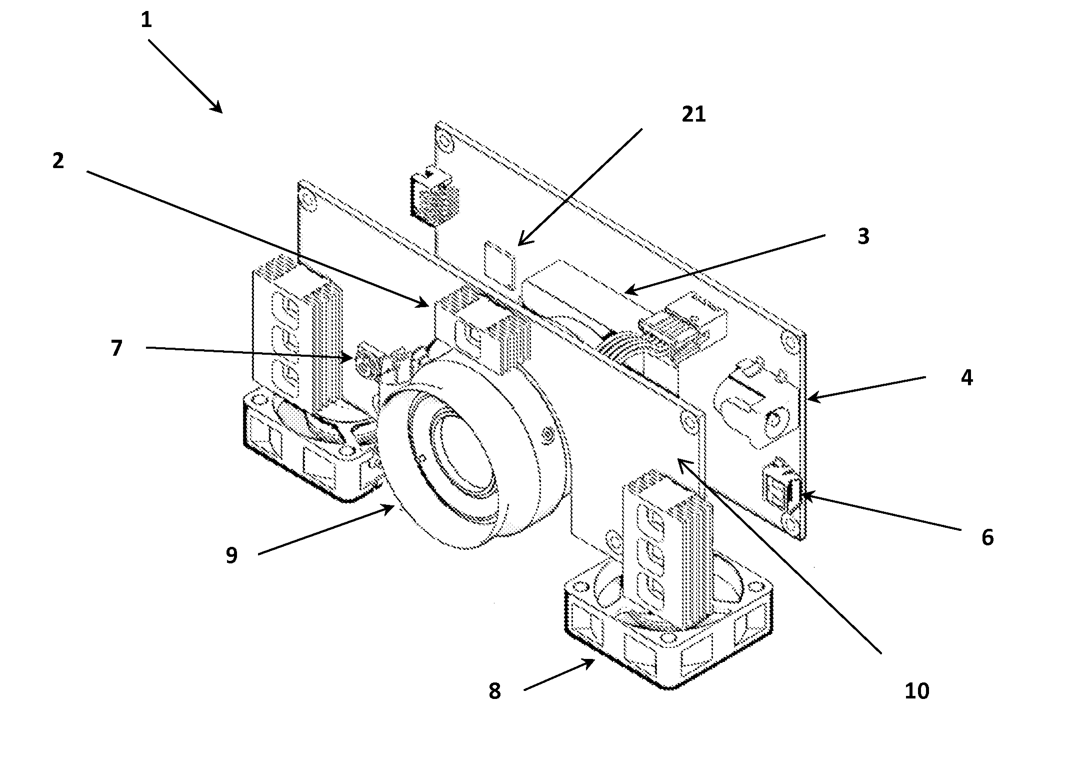
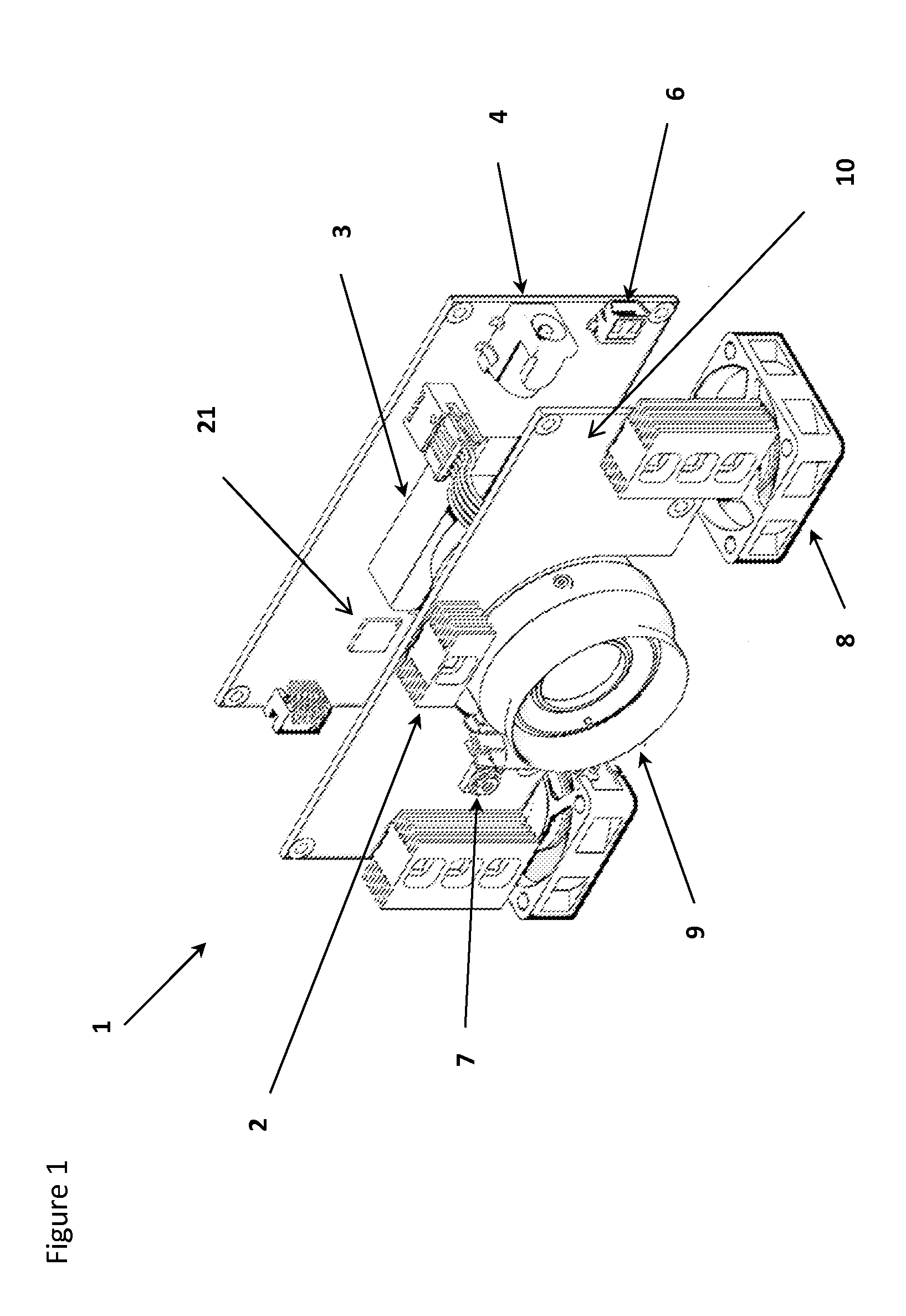
[0033]With reference to FIG. 1, a depth camera 1, in accordance with the present invention, for a Time of Flight (ToF) system, e.g. for a gesture recognition device, includes a light source 2, e.g. an LED, Laser or other light emitting device with associated drive and control circuitry, for launching a beam of light into an overall Range of Interest (RoI) and Field of View (FoV), a receiving optic with an IR filter, and a depth sensor detector array 3 for receiving and detecting portions of the beam of light reflected off of various moving objects within the RoI and FoV. The depth camera 1 also includes a power port 4 for connection to a remote or host power supply, and a data port 6 for connection to a host processor. In the illustrated application, a color (RGB) camera 7 is also provided, along with variable speed fans 8 for cooling the system.

[0034]When considering dynamic range and depth of field, higher frequencies and lower powers work well for short range applications (0.5 mm...


PUM


Abstract

In order to maximize the dynamic range and depth of field for a depth camera used in a time of flight system, the light source is modulated at a plurality of different frequencies, a plurality of different peak optical powers, a plurality of integration subperiods, a plurality of lens foci, aperture and zoom settings during each camera frame time. The different sets of settings effectively create subrange volumes of interest within a larger aggregate volume of interest, each having their own frequency, peak optical power, lens aperture, lens zoom and lens focus products consistent with the distance, object reflectivity, object motion, field of view, etc. requirements of various ranging applications.

Description

CROSS-REFERENCE TO RELATED APPLICATIONS[0001]The present invention claims priority from U.S. patent application Ser. No. 61 / 594,745 filed Feb. 3, 2012, which is incorporated herein by reference.TECHNICAL FIELD[0002]The present invention relates to a high dynamic range and depth of field depth camera, and in particular to a depth camera, which has a plurality of frequency, peak optical power and integration period settings within each frame time for use in a time of flight based camera system.BACKGROUND OF THE INVENTION[0003]In traditional photography, depth of field (DOF) is how much of your image is in focus. Shallow depth of field refers to when only things that are very close to the plane of the subject you focus on are in focus. Objects that are behind or in front of your subject will appear out of focus. Dynamic range refers to the difference between your highlights and shadows in an image. On average, the human eye can see dynamic range on the order of 1,000,000:1. What this m...

Claims


Application Information

Patent Timeline
Patent Type & Authority Applications(United States)
IPC IPC(8): H04N13/02G01S17/894
CPCH04N13/0203G01S17/89G01S7/4868G01S7/484G01S7/4814H04N13/204G01S17/894
Inventor BILLERBECK, BRYEDTIEN, AN-CHUNMORALES, LUCAS
Owner LUMENTUM OPERATIONS LLC
Learn More