
Computer mouse peripheral

a peripheral and mouse technology, applied in the direction of instruments, cathode-ray tube indicators, electric digital data processing, etc., to achieve the greatest degree of comfort and control, convenient recall, and convenient operation

Inactive Publication Date: 2013-08-01
SWIFTPOINT LTD
View PDF4 Cites 14 Cited by
  • Summary
  • Abstract
  • Description
  • Claims
  • Application Information

AI Technical Summary

Benefits of technology

The patent is for a device with surfaces that users' digits can engage with to operate it. These surfaces are designed to be at least partially recessed, which helps position and keep the digits in place while using the device. However, in some cases, the engaging surfaces may be protruding or flush with the rest of the device. The device can also lock scrolling in a specific direction, allowing users to perform more comfortable and ergonomic movements while scrolling through documents.

Problems solved by technology

Although the forerunner of the modern computer mouse was devised over 40 years ago by Doug Engelbart, the first major commercial implementation was delayed until 1983 with the advent of the Apple Macintosh™ computer.
Nevertheless, the overwhelming majority of computers produced today still issue with a keyboard and mouse as the major human / computer interface.
Nevertheless, the conventional mouse design exhibits numerous disadvantages including;The need for the user to remove a hand from the keyboard to manipulate the mouse, resulting in reduced efficiency and increased physical labour,forcing the user's hand / arm to adopt a strained position, including the repetitive use of a single finger combined with an awkward hand grip,unsuitability for use with laptop and other portable computer devices due to the need for a flat firm surface adjacent the computer,difficulty in replicating the fine free-hand movements easily performed by a user with a pen or brush.
Even accomplished computer users have great difficulty reproducing legible handwriting, drawing circles or the like with a mouse,Scrolling over large distances or moving the mouse pointer over large areas often requires a conventional mouse to be lifted off its support surface and moved in the opposite direction to avoid running out of space.
Conventional mouse designs are not conducive to being readily lifted from the surface, particularly if one of the mouse buttons is being activated simultaneously, e.g. in selecting portions of text.
However, the mouse disclosed by Lo constrains the fingers to maintain a substantially extended position, preventing the relaxed, curled position of a hand at repose.
Whilst this configuration may possibly address one ergonomic aspect of conventional mouse configurations, it does not address any of the remaining deficiencies outlined above.
The device is incapable of controlled positioning movement solely by the thumb or from being grasped in a ‘pen-like’ grip to facilitate fine movement control of writing.
The device dimensions required to provide a contact grip for the user's whole hand also preclude its effective use in restricted workspace environments such as on laptop computers.
Whilst the ergonomics of the mice disclosed provides an improvement over some deficiencies of conventional mice, each design is still dimensioned and configured for use by the whole of the user's hand above a work surface adjacent the keyboard and as such still require the inefficiencies and ergonomic stresses of keyboard-mouse hand movements.
However, accurate cursor control is difficult to achieve when performed in free space without the support of a work surface or the like.
Furthermore, the device is designed to be securely attached to the user's thumb and may not be readily removed if the user wishes to undertake non-computing activities without inconvenience.
Nevertheless, each design still requires the user to remove their hand from the keyboard to acquire the device before performing mouse operations.
Furthermore, due to the reduced size of the devices, detecting the mouse location with the user's peripheral vision would in fact be more difficult, thus increasing the potential inefficiencies involved.
Although the use of a conventional mouse cable between the host computer and the mouse does provide further visual clues to the mouse location, this electrical cable reduces the flexibility of the device in comparison to wireless embodiments.
Although wireless embodiments are also disclosed, these mouse embodiments would be even more difficult to locate and may be easily misplaced amidst other user work surface items.
Moreover, although it is conceivable the devices may be used over the surface of the keyboard, there is no means of retaining the mouse to the user's hand and thus it would still be necessary to move the device from the keyboard during typing or risk its interference with the typing keystrokes.
Moreover, prior art without a means of stabilizing the pointing device during activation of the mouse buttons increases the likelihood of disturbing the device position during the button ‘clicking’ action.
As mouse buttons are often operated during activities where cursor placement is key (during selection and insertion), this is a further disadvantage.
Consequently, it is not possible to operate the mouse in a pen-like grip to achieve fine movement control, nor can the mouse buttons be readily operated by a pinching action between the thumb and fingers.
Moreover, movement of the mouse requires the movement of the whole user's hand.
However, the device is incapable of controlled movement solely by the user's thumb and is unsuited to movement over constricted work surfaces due to its relatively large size and modes of operation.
The device configuration however prevents controlled movement of the device solely via the user's thumb, or the stabilising of the device with the thumb during operation of the mouse buttons.
A pen-like grip for writing applications is also clearly incompatible with the pyramidally-shaped exterior.

Method used


Image

  • Computer mouse peripheral
  • Computer mouse peripheral
  • Computer mouse peripheral

Examples


Embodiment Construction

Best Modes for Carrying Out the Invention

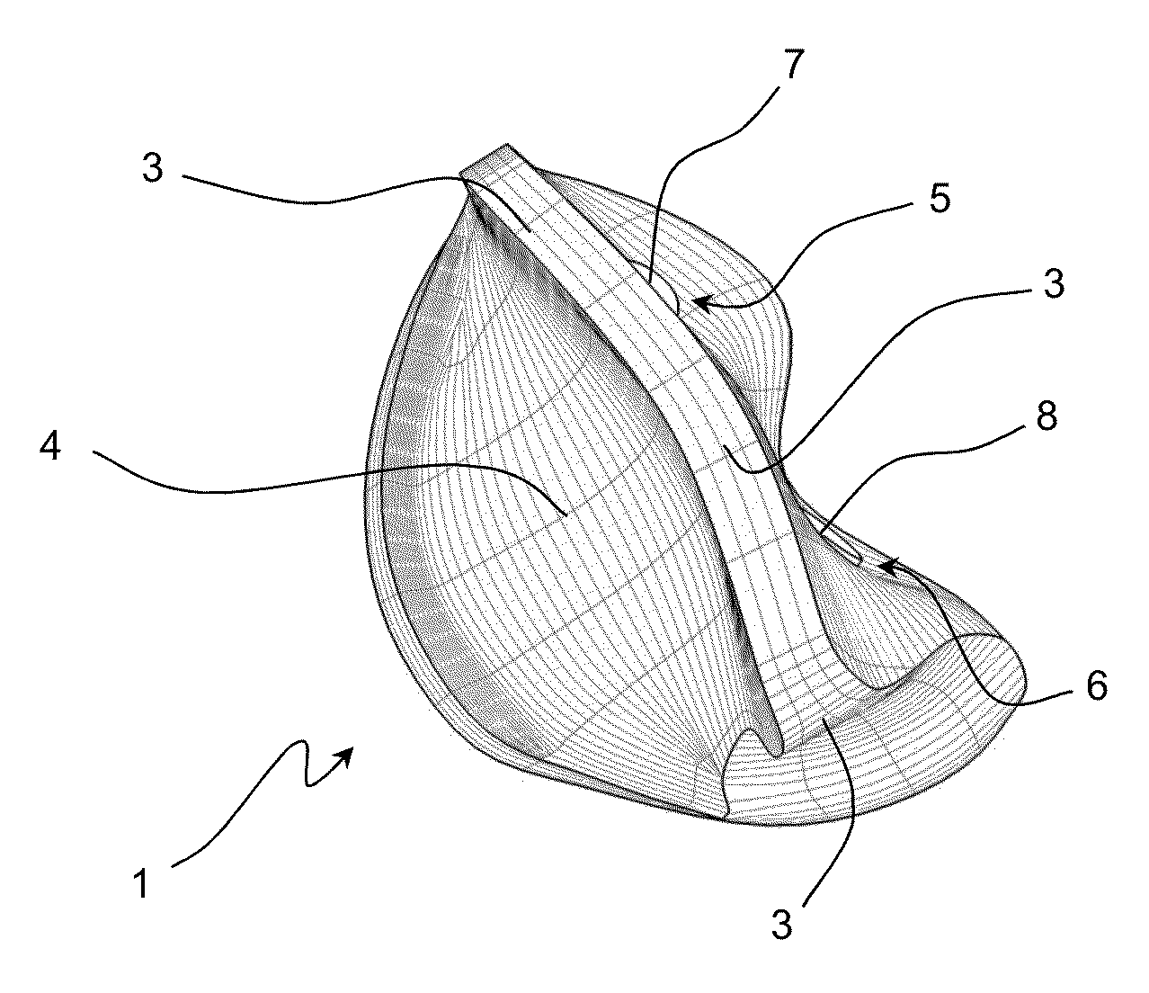
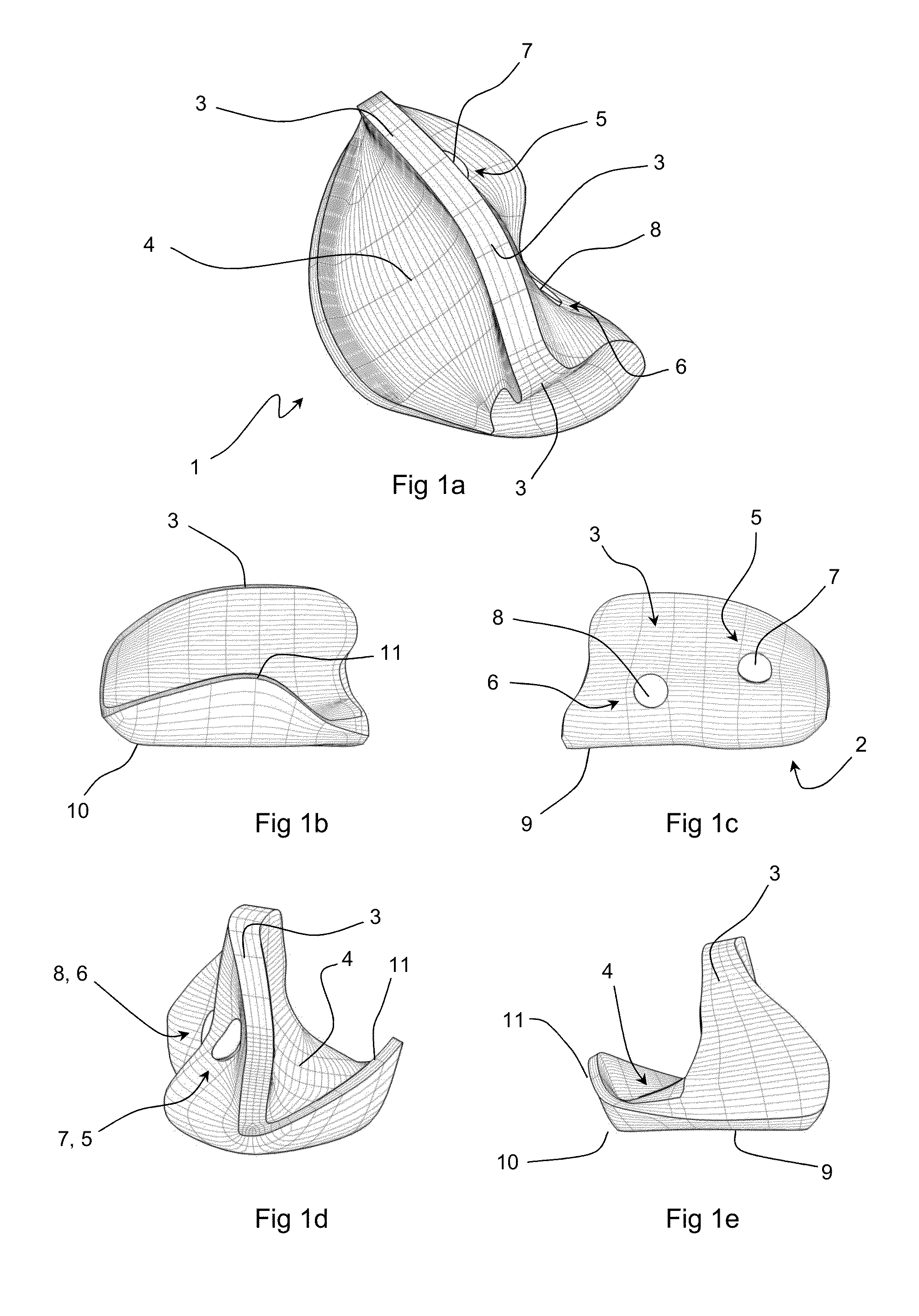
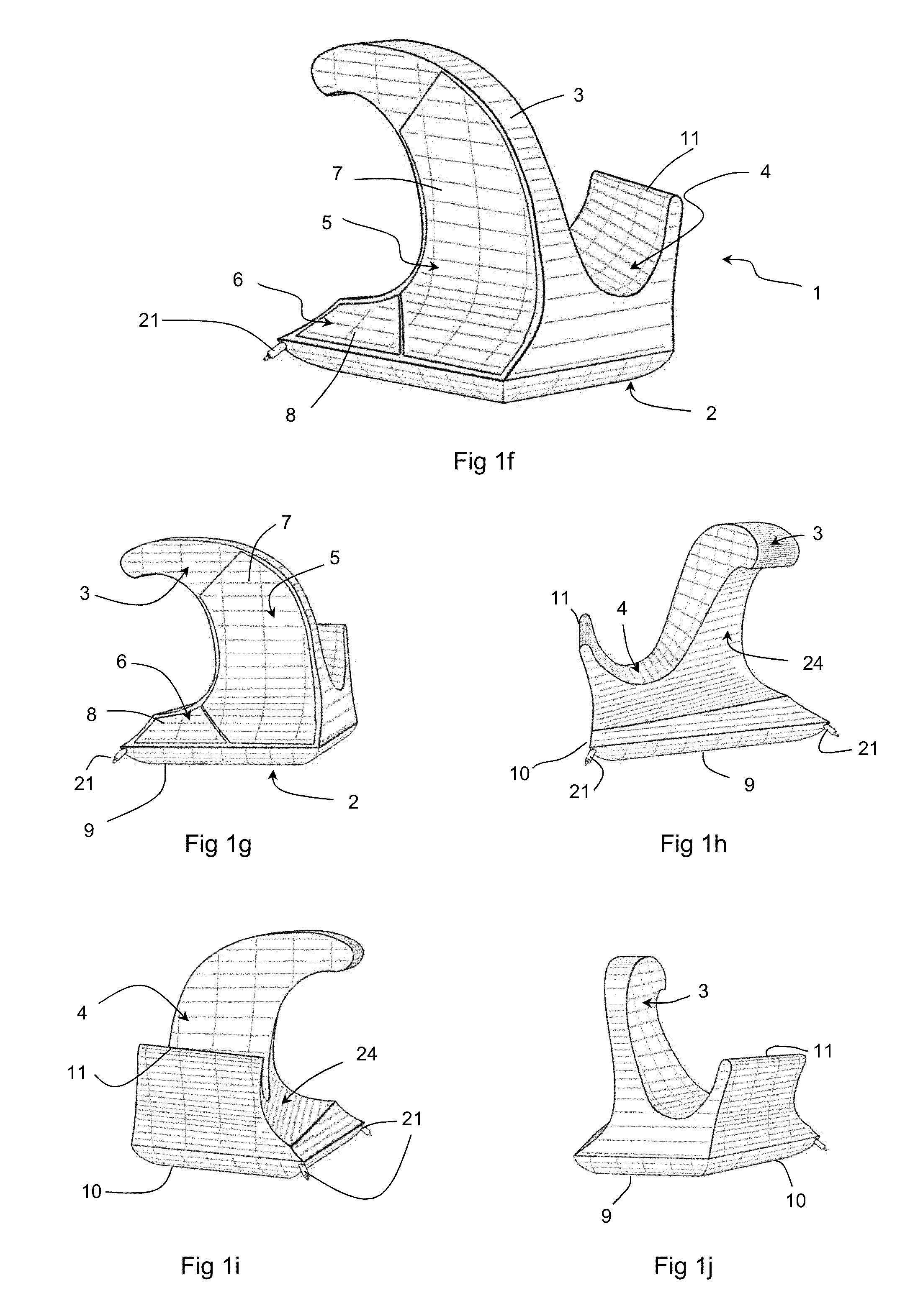
[0267]FIGS. 1-23 show preferred embodiments of the present invention of a computer mouse input device configured with a base portion (2) having a substantially planar lower surface (with the exception of the embodiments shown in FIGS. 6 and 20) and a spine portion (3) projecting substantially upward from the base portion (2). The embodiment demonstrated in FIGS. 1-5 shows a device (1) optimised for use by a right-handed user and includes an elongated thumb-engaging surface (4) on a first lateral side of the spine portion (3) and an index fingertip-engaging surface (5) and a middle fingertip-engaging surface (6) located on an opposing lateral side of spine (3) to the thumb-engaging surface (4). Alternative embodiments configured for left-handed users and ambidextrous embodiments are also possible as described more fully below. Contact sensors (7, 8) are located in the index fingertip-engaging surface (5) and a middle fingertip-engaging surface...


PUM


Abstract

A computer pointing device including: a base portion with a lower surface adapted for sliding across a work surface, a spine portion, projecting substantially upward from said base portion and having a thumb-engaging surface on a first lateral side of the spine and at least one index fingertip and / or middle fingertip-engaging surface on a second lateral side of the spine opposing said first lateral side. A keyboard with an altered arrangement of function of keys, such as an enlarged or truncated or no spacebar or capable of an altered appearance in accordance with keys being re-mapped to sensors on a pointing device. A keyboard with a virtual screen display, which may be made semi-transparent by activating a sensor on a pointing device. A computer with a recess capable of accommodating a mouse device. A locked scrolling or zooming means, using any pointing device, in which scrolling or zooming in a defined direction is proportional to the distance travelled by the device, irrespective of direction of movement of the device.

Description

CROSS-REFERENCE TO OTHER APPLICATIONS[0001]This is a continuation of U.S. patent application Ser. No. 11 / 815,094, filed on Dec. 2, 2008, which is a National Phase of International Application No. PCT / NZ2006 / 000007, filed on Jan. 30, 2006, which claims priority from New Zealand Patent Application No. 535766, filed on Jan. 30, 2005, all of which are incorporated herein by reference in their entirety.TECHNICAL FIELD[0002]The present invention relates generally to a computer pointing device. Comparable known representative devices are commonly known as ‘mice’, trackballs, joysticks, touch screens, touch pads and the like, and are collectively referred to as pointing devices.BACKGROUND ART[0003]Although the forerunner of the modern computer mouse was devised over 40 years ago by Doug Engelbart, the first major commercial implementation was delayed until 1983 with the advent of the Apple Macintosh™ computer. This was followed several years later by the widespread adoption of the Windows™ ...

Claims


Application Information

Patent Timeline
Patent Type & Authority Applications(United States)
IPC IPC(8): G06F3/0354
CPCG06F1/162G06F1/169G06F1/1692G06F2203/0335G06F3/03545G06F3/04886G06F2203/0333G06F3/03543G06F3/041
Inventor ODGERS, GRANT NEVILLE
Owner SWIFTPOINT LTD
Learn More