
Shop assembled vertical serpentine flow molten salt solar receiver

a solar receiver and shop-assembled technology, applied in the field of modular solar receivers, can solve the problems of inability to maintain demand, inability to economically store energy, and fluctuations in the grid due to cloud passages, and achieve the effect of modular design and simple design

Active Publication Date: 2013-08-01
THE BABCOCK & WILCOX CO
View PDF10 Cites 24 Cited by
  • Summary
  • Abstract
  • Description
  • Claims
  • Application Information

AI Technical Summary

Benefits of technology

The patent describes small, modular solar receivers that can be easily transported and assembled in the field, reducing field costs. These modular units can be used in a heliostat field and multiple units can be used to generate more power. The patent also includes molten salt solar power systems that use these modular units. The "modular" term is used to describe a standardized unit that can be easily added to increase the scale of the system. Overall, the patent aims to provide a more efficient and cost-effective way to use solar energy for power generation.

Problems solved by technology

Currently wind and solar photovoltaic power generators do not have economical energy storage capability.
Without energy storage, fluctuations on the grid are inevitable due to changing winds, clouds, and darkness at night.
As more solar electricity power generators are installed, fluctuations in the grid due to cloud passages and daily start up and shut down will be unacceptable to maintain demand.
A solar power plant that uses steam / water receivers and separately uses molten salt for thermal storage is possible, but less efficient.
Some problems with this system include the added cost of additional heat exchangers.
Also, it would be difficult to design a steam / water receiver that is capable of producing hot enough steam to fully utilize the high temperature storage capability of the salt.
Different heat transfer fluids (HTF) could be used for energy storage, such as oils used with parabolic trough technology, however these HTFs are limited to lower temperatures and are less efficient.
Overall solar power plant efficiency would be lost through the additional heat exchangers and temperature limitations of different HTFs.

Method used


Image

  • Shop assembled vertical serpentine flow molten salt solar receiver
  • Shop assembled vertical serpentine flow molten salt solar receiver
  • Shop assembled vertical serpentine flow molten salt solar receiver

Examples


Embodiment Construction

[0064]A more complete understanding of the processes and apparatuses disclosed herein can be obtained by reference to the accompanying drawings. These figures are merely schematic representations based on convenience and the ease of demonstrating the existing art and / or the present development, and are, therefore, not intended to indicate relative size and dimensions of the assemblies or components thereof.

[0065]Although specific terms are used in the following description for the sake of clarity, these terms are intended to refer only to the particular structure of the embodiments selected for illustration in the drawings, and are not intended to define or limit the scope of the disclosure. In the drawings and the following description below, it is to be understood that like numeric designations refer to components of like function.

[0066]The modifier “about” used in connection with a quantity is inclusive of the stated value and has the meaning dictated by the context (for example,...


PUM


Abstract

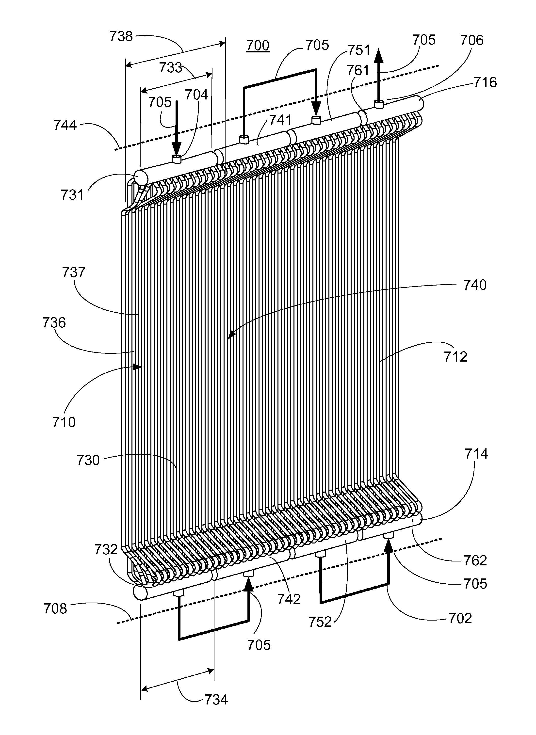
A solar receiver is disclosed. The solar receiver is modular, has multiple tube panels in a rectangular / square / polygonal / circular configuration, and is designed for use with molten salt or another heat transfer fluid. The heat transfer fluid flows in a vertical serpentine path through the sides (facets) of the solar receiver. The solar receiver can be shop assembled and can be used with a support tower to form a solar power system.

Description

[0001]This application claims priority to U.S. Provisional Patent Application Ser. No. 61 / 513,251 filed Jul. 29, 2011, the disclosure of which is hereby fully incorporated by reference.BACKGROUND OF THE INVENTION[0002]The present disclosure relates, broadly, to the field of power generation used to produce electricity. More particularly, the disclosure relates to a modular, shop-assembled solar receiver. The receiver comprises an arrangement of heat transfer surfaces or facets, a molten salt heat transfer system structurally and fluidically interconnected thereto, and an integral support structure, among other components. Also disclosed is a power generation system using such a shop-assembled solar receiver.[0003]Generally, a solar receiver is a component of a solar energy generation system whereby radiation from the sun (i.e. sunlight) is used as a heat source. The radiation and heat energy from the sun is transferred to a working fluid which is used to ultimately generate electric...

Claims


Application Information

Patent Timeline
IPC IPC(8): F24J2/10F24J2/34F24J2/30F24J2/24F24S10/30F24S10/70F24S20/20F24S23/70
CPCF22B1/006F24J2/07F24J2/4649F24J2/10Y02E10/41F24J2/30F24J2/34Y02E10/44F24J2/245F24S60/00F24S20/20F24S23/70F24S10/742F24S80/20F24S10/30Y02E10/40
Inventor WASYLUK, DAVID T.KRAFT, DAVID L.MARSHALL, JASON M.IANNACCHIONE, STEVEN P.
Owner THE BABCOCK & WILCOX CO
Learn More