
Full-digital clock correction circuit and method thereof

a technology of digital clock and correction circuit, which is applied in the direction of pulse automatic control, pulse manipulation, pulse technique, etc., can solve the problems of inability to adopt the positive and negative edges of clock signals for accelerating digital data extraction, errors may occur during data acquisition, and the cycle of clock signals in digital devices is not equal to 50%, so as to improve the duty-cycle correction accuracy and widen the frequency operating range , the effect of wide duty-cycle range of input clock

Active Publication Date: 2013-07-25
NATIONAL CHUNG CHENG UNIV
View PDF0 Cites 2 Cited by
  • Summary
  • Abstract
  • Description
  • Claims
  • Application Information

AI Technical Summary

Benefits of technology

[0007]An objective of the present invention is to provide a full-digital clock duty cycle correction circuit and a method thereof, which improve duty-cycle correction accuracy and provide a wider frequency operating range. In addition, the present invention also supports a wider duty-cycle range of the input clock and reduces the chip area.

Problems solved by technology

Nonetheless, owing to imbalanced charge and discharge time via transistors and variations in process, temperature, and operating voltage, the duty cycle of clock signals in digital devices is not equal to 50%.
Thereby, it is not possible to adopt the positive and negative edges of clock signals for accelerating digital data extraction.
Besides, errors may occur during data acquisition .
Furthermore, by using the TDC architecture, the half-cycle delay circuit has to be included, which makes the tuning accuracy of the digital DCC become twice the accuracy of the TDC, and hence limiting the accuracy of the digital DCC and resulting in excessive error in duty cycle.

Method used


Image

  • Full-digital clock correction circuit and method thereof
  • Full-digital clock correction circuit and method thereof
  • Full-digital clock correction circuit and method thereof

Examples


Embodiment Construction

[0015]In order to make the structure and characteristics as well as the effectiveness of the present invention to be further understood and recognized, the detailed description of the present invention is provided as follows along with embodiments and accompanying figures.

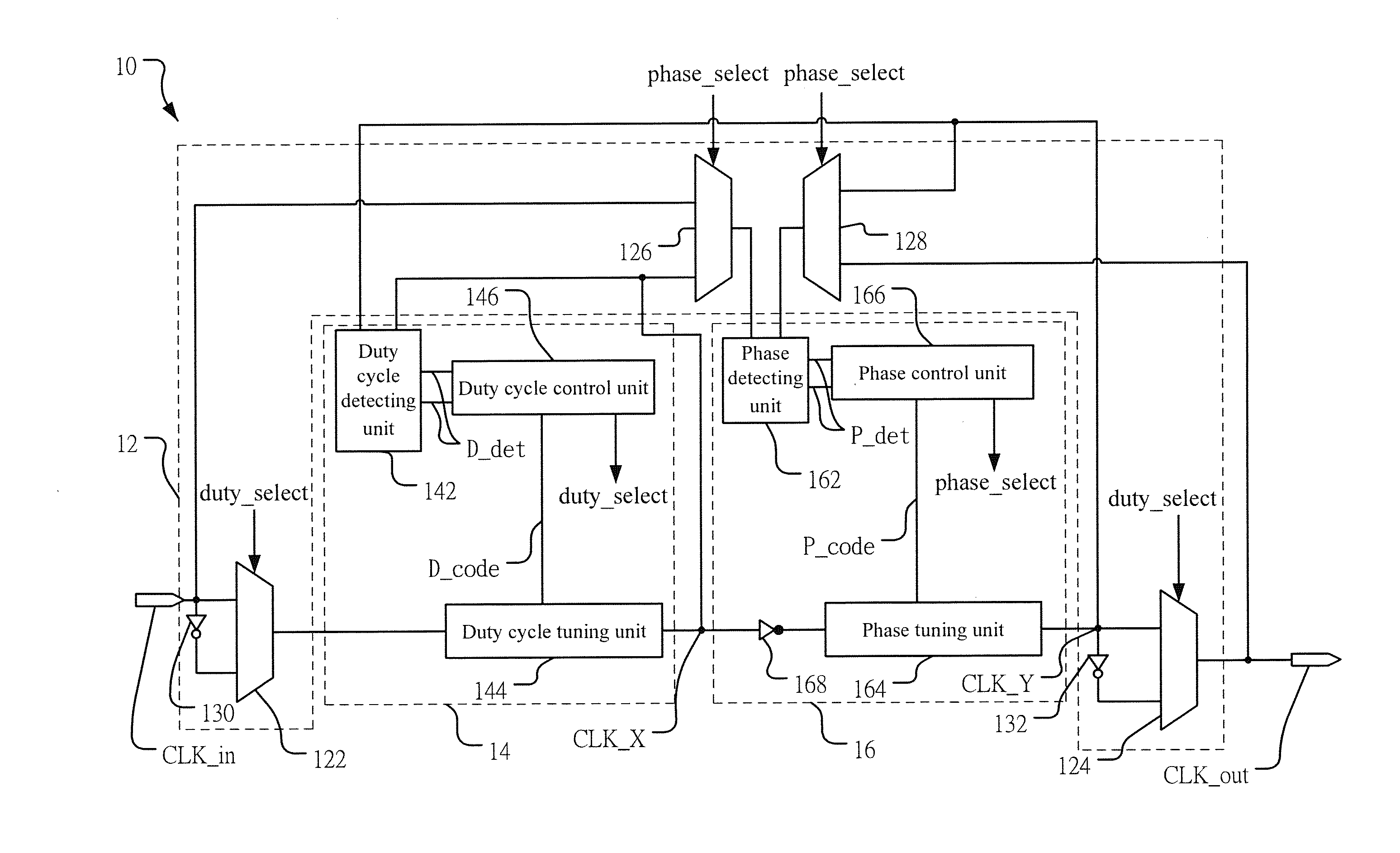
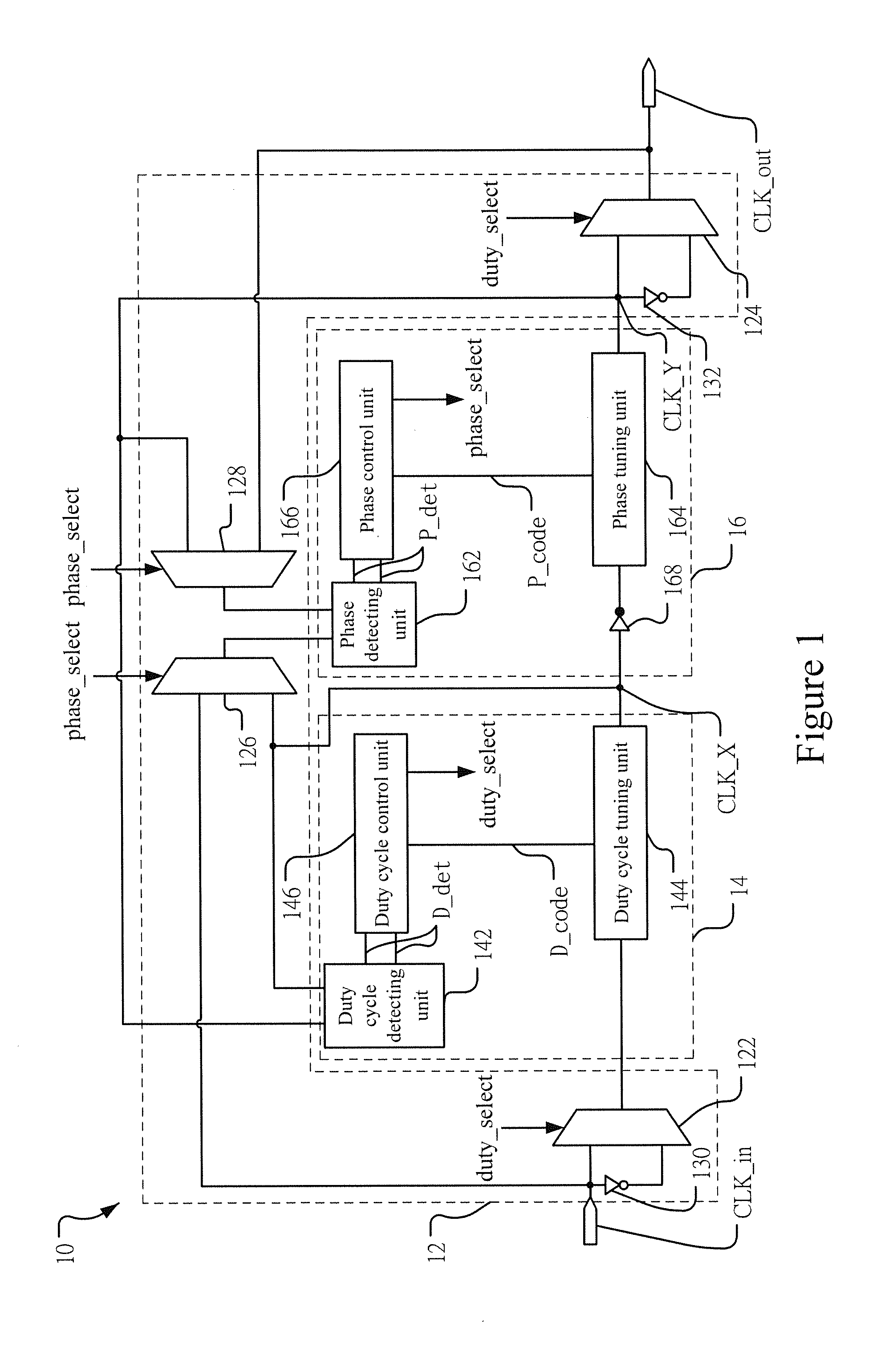
[0016]FIG. 1 shows a circuit diagram according to an embodiment of the present invention. As shown in the figure, the full-digital clock duty cycle correction circuit 10 according to the present invention comprises a sampling unit 12, a duty cycle correcting module 14, and a phase-lock module 16. In addition, the sampling unit 12 further comprises a first multiplexer 122, a second multiplexer 124, a third multiplexer 126, a fourth multiplexer 128, a first inverter 130, and a second inverter 132. The duty cycle correction module 14 further comprises a duty cycle detecting unit 142, a duty cycle tuning unit 144, and a duty cycle control unit 146. Besides, the phase-lock module 16 further comprises a phase detecting u...


PUM


Abstract

The present invention provides a full-digital clock duty cycle correction circuit and a method thereof. The circuit comprises a sampling unit, a duty cycle correcting module, and a phase-lock module. The duty cycle correcting module produces a first clock signal according to an input clock signal. The phase-lock module produces a second clock signal according to the first clock signal and is used for aligning the positive edges of the clock signals. The duty cycle correcting module adjusts the pulse width of the first clock signal according to the clock signals. In addition, after the pulse width is adjusted, the positive edges of the clock signals are re-aligned. When the pulse width is not equal to zero, the pulse width is re-adjusted and the positive edges are re-aligned until the pulse widths of the clock signals are identical. Finally, the second clock signal is outputted and thus producing a clock signal having 50% duty cycle.

Description

FIELD OF THE INVENTION[0001]The present invention relates generally to a duty cycle correction device and a method thereof, and particularly to a full-digital clock duty cycle correction circuit and a method thereof.BACKGROUND OF THE INVENTION[0002]Digital devices are prevalent nowadays. While spreading, exchanging, and processing digital information using digital devices, it is necessary to operate in coordination with clocks in circuits for processing digital signals or even the data attached in digital signals. For example, the central processing unit (CPU) in computer architecture should operate in coordination with the clock signal for driving the various digital circuits inside the CPU to operate in coordination with the clock signal for accessing data, processing data, or controlling hardware. In addition, in mobile devices, it is also required to use clocks for triggering transmission of digital information; synchronization in clocks is required before correct data access be...

Claims


Application Information

Patent Timeline
Patent Type & Authority Applications(United States)
IPC IPC(8): H03L7/091
CPCH03K5/1565
Inventor CHUNG, CHING-CHESHEN, SUNG-EN
Owner NATIONAL CHUNG CHENG UNIV
Learn More