
High-power direct current/square wave changing circuit and control method therefor

A conversion circuit and high-power technology, which is applied in the field of high-power DC/square wave conversion circuit and its control, can solve the problems of the highest frequency and minimum duty ratio limitation, the inability to output asymmetric voltage pulse voltage waveform, etc., and achieve waveform quality High, positive and negative pulse conversion speed is fast, the effect of a large duty cycle range

Active Publication Date: 2012-08-22
SOUTH CHINA UNIV OF TECH
View PDF3 Cites 0 Cited by
  • Summary
  • Abstract
  • Description
  • Claims
  • Application Information

AI Technical Summary

Problems solved by technology

However, due to the charging and discharging effect of the large capacitor on the bus, the output voltage has a large rise time delay and a large fall time delay, and cannot output a pulse voltage waveform with a large asymmetrical voltage difference or a small duty ratio. duty cycle is limited

Method used


Image

  • High-power direct current/square wave changing circuit and control method therefor
  • High-power direct current/square wave changing circuit and control method therefor
  • High-power direct current/square wave changing circuit and control method therefor

Examples


Embodiment Construction

[0023] The present invention will be further described below in conjunction with specific examples.

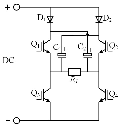
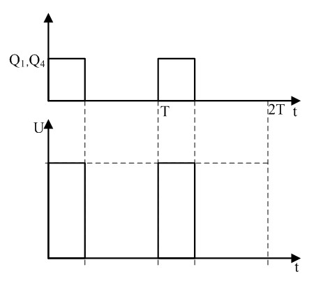
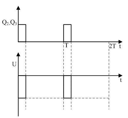
[0024] figure 1 It is an example diagram of a high-power DC / square wave conversion circuit according to an embodiment of the present invention. The high-power DC / square wave conversion circuit includes four switching tubes: the first switching tube Q 1 , the second switching tube Q 2 , the third switching tube Q 3 , the fourth switching tube Q 4 , two fast recovery diode modules: the first fast recovery diode module D 1 , the second fast recovery diode module D 2 , two capacitor modules: the first capacitor module C 1 , the second capacitor module C 2 ; The four switching tubes Q 1 -Q 4 The first switching tube Q in 1 and the third switching tube Q 3 The first side bridge arm of the H-bridge circuit is formed in series, and the connection is led out to be the output end of the first side bridge arm of the H-bridge circuit; the first switch tube Q 1 of the high side ...


PUM


Abstract

The invention discloses a high-power direct current / square wave changing circuit and a control method for the high-power direct current / square wave changing circuit. The high-power direct current / square wave changing circuit comprises four switch tubes, two fast-recovery diode modules and two capacitor modules, wherein the first switch tube and the third switch tube are connected in series to form a first side bridge arm of an H bridge, and the connecting position is an output end; a high end of the first switch tube is connected with an cathode of a first fast-recovery diode, the second capacitor is connected with an output end of a second side bridge arm at the connecting position; the second switch tube and the fourth switch tube are connected in series to form the second bridge arm, and the connecting position is an output end; a high end of the second switch tube is connected with a cathode of a second fast-recovery diode, and a first capacitor is connected with an output end of the first side bridge arm at the connecting position; and anodes of the two fast-recovery diodes are connected with a direct-current bus, and low ends of the third switch tube and the fourth switch tube are connected with a cathode of the direct-current bus. The control method is simple, the width, the frequency and the amplitude of output square-wave pulses can be regulated, and therefore, the output square-wave pulse has the advantages that the range of the duty ratio is large, the switching speed of a positive pulse and a negative pulse is high, etc.

Description

technical field [0001] The invention relates to a high-frequency pulse power supply for multiple industries and purposes, in particular to a high-power DC / square wave conversion circuit and a control method thereof. Background technique [0002] Pulse power supply is widely used in electroplating gold, silver, tin, alloys, etc., and plays a very important role in improving the coating. The electroplating of double-pulse power supply is more detailed and smoother than that of single-pulse power supply, and some special electroplating needs special voltage waveforms, such as positive and negative asymmetrical pulses. In order to meet the requirements of this special voltage waveform, most of the current domestic pulse power supply output part adopts H-bridge circuit structure. In order to improve the waveform, absorb voltage spikes, and protect the switching tube, it is usually necessary to increase the capacity capacitor on the busbar of the H-bridge. However, due to the cha...

Claims


Application Information

Patent Timeline
Patent Type & Authority Applications(China)
IPC IPC(8): H02M9/00
Inventor 杜贵平
Owner SOUTH CHINA UNIV OF TECH
Learn More