
Device and method for powder distribution and additive manufacturing method using the same

a technology of additive manufacturing and powder distribution, which is applied in the field of powder distribution devices and methods, can solve the problems of difficult or impossible production of relatively complex three-dimensional structures such as inner cavities and inner channels of lbam

Active Publication Date: 2013-07-25
IND TECH RES INST
View PDF16 Cites 148 Cited by
  • Summary
  • Abstract
  • Description
  • Claims
  • Application Information

AI Technical Summary

Benefits of technology

The present invention provides a powder distribution method and device that allows different kinds and particle sizes of powders to be mixed uniformly by rotating a receptacle, and then poured out and piled up on a specific position by the rotation movement of the receptacle. This allows for a more compact layer of distributed powder to be formed on a working area by a linear translation movement of the receptacle. In one embodiment, the method includes using a translation driver for driving the receptacle to move to different positions and a rotation driver for driving the receptacle to rotate to enable the powder to be poured out and deposited on a specific position, resulting in improved compactness of the layer formed by the distributed powder.

Problems solved by technology

It is noted that LBAM can produce relatively complex three-dimensional structures like inner cavities and inner channels, which are normally difficult or impossible for traditional manufacturing technologies based on material removal.
However, there are still issues to be solved for improving the current additive manufacturing technique, such as how to increase the density of the part being built, how to increase the uniformity of deposition, how to get improvement in the geometrical accuracy of the part being built, and how to eliminate the thermal deformation due to the temperature variation in the ambience, and so on.

Method used


Image

  • Device and method for powder distribution and additive manufacturing method using the same
  • Device and method for powder distribution and additive manufacturing method using the same
  • Device and method for powder distribution and additive manufacturing method using the same

Examples


Embodiment Construction

[0026]For your esteemed members of reviewing committee to further understand and recognize the fulfilled functions and structural characteristics of the disclosure, several exemplary embodiments cooperating with detailed description are presented as the follows.

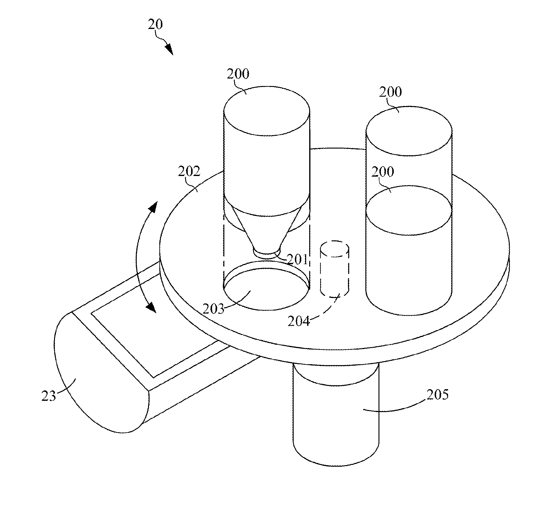
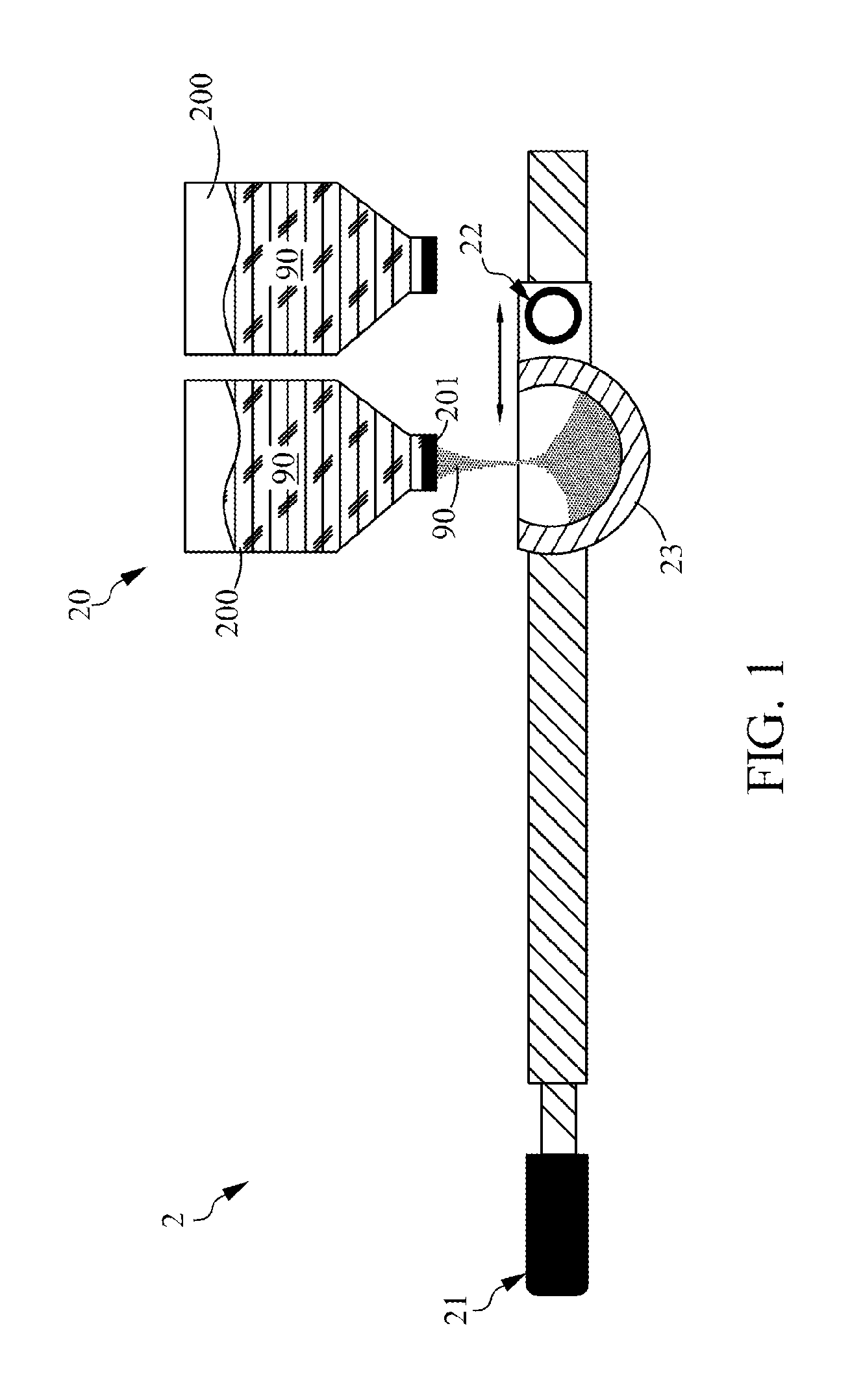
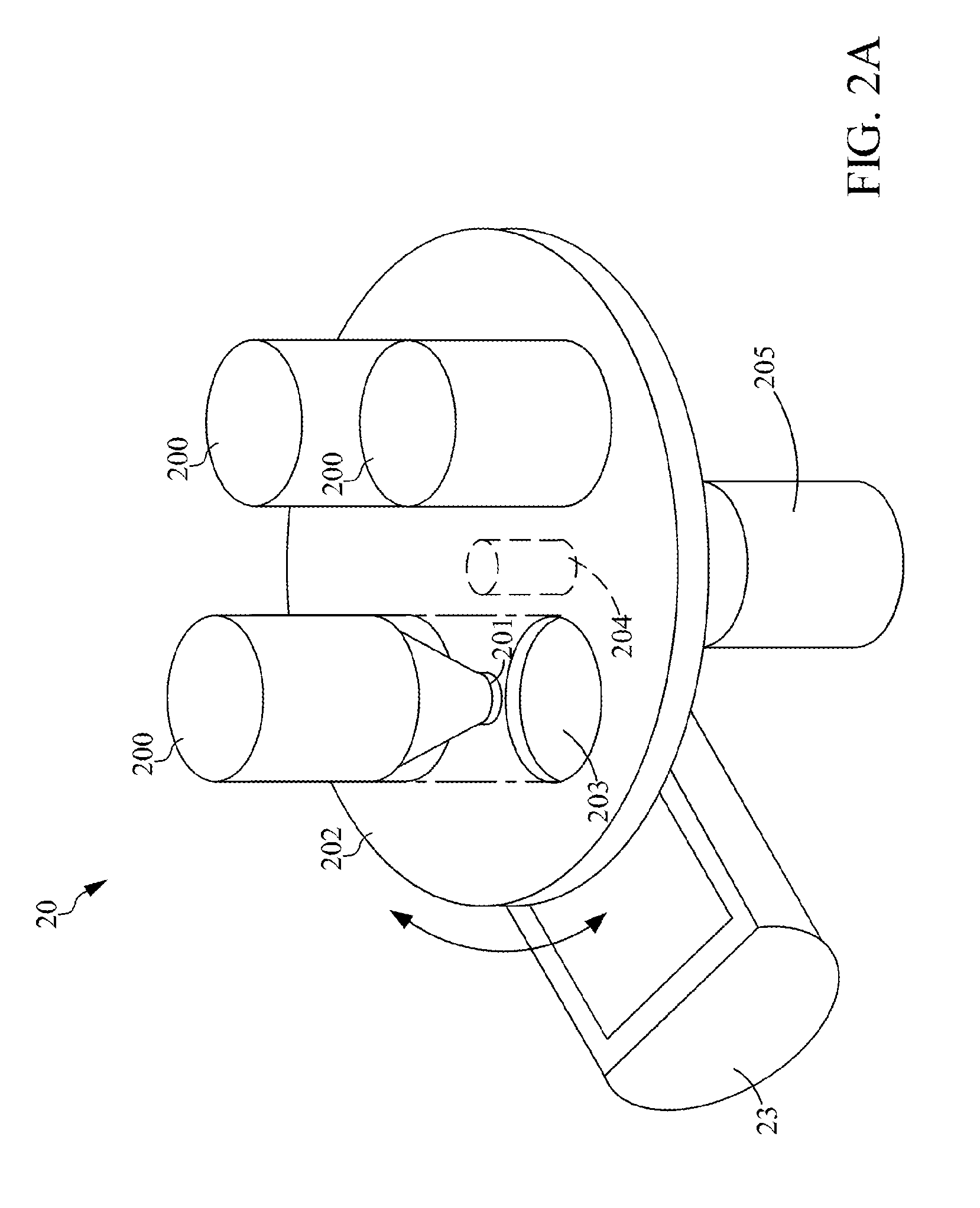
[0027]Please refer to FIG. 1, which is a schematic diagram showing a powder distribution device according to an exemplary embodiment of the present disclosure. As shown in FIG. 1, the powder distribution device 2 comprises: a feeder 20, a translation driver 21, a rotation driver 22 and a receptacle 23, whereas the feeder 20 is used for providing at least one powder 90. In this exemplary embodiment, the feeder 20 is further configured with at least one container 200, while each container 200 is further formed with at least one feeding port 201. In a condition when there is only one such container 200 in the receptacle 20, the container 200 can be used for storing a single kind of powder or a mixture of different kinds of powde...


PUM

PropertyMeasurementUnit
Temperatureaaaaaaaaaa
Thicknessaaaaaaaaaa
Forceaaaaaaaaaa

Abstract

The present disclosure provides a device and method for powder distribution and an additive manufacturing method, wherein different size or kind of powders could be chosen to be accommodated within a receptacle. The receptacle can uniformly mix the powder by a rotation movement, pour out the powders by the rotation movement and distribute the powders for forming a layer by a translation movement. In another embodiment, the receptacle further comprises a heating element for preheating the powders. Not only can the present disclosure uniformly mix the powders so as to reduce the thermal deformation and distribute the powder layer compactly, but also can the present disclosure distribute different kinds of powder in different layer so as to increase the diversity in additive manufacturing.

Description

FIELD[0001]The present disclosure relates to a device and method for powder handling, and more particularly, to a device and method for powder distribution and an additive manufacturing method using the same.BACKGROUND[0002]The term additive manufacturing describes technologies which can be used anywhere throughout the product life cycle from pre-production (i.e. rapid prototyping) to full scale production (also known as rapid manufacturing) and even for tooling applications or post production customization. Accordingly, Additive manufacturing (AM) is defined as the process of joining materials to make objects from 3D model data, usually layer upon layer, as opposed to subtractive manufacturing methodologies, such as traditional machining. The first successful attempts at additive manufacturing came from technology developed in the 1970s, and since then the additive manufacturing technology is developing rapidly with increasing industrial applications. Nowadays, there are already a ...

Claims


Application Information

Patent Timeline
IPC IPC(8): B65B1/04B22F1/00
CPCB32B19/00B29C64/153B33Y30/00B33Y40/00B29C64/205B29C64/236B29C64/241B29C64/329Y02P10/25B01F31/10B22F12/58B22F10/28B22F12/13B22F12/226B22F12/55B22F10/34B22F12/224B22F12/60B22F12/90B33Y40/10B22F1/00B23K26/342B23K26/702B05C19/005B05C19/008B05C19/06
Inventor ZHUANG, CHUAN-SHENGLIN, CHING-CHIHLIN, STEVENTAI, WEI-LUNTSENG, WEN-PENGHORNG, JI-BIN
Owner IND TECH RES INST
Learn More