Tissue harvesting apparatus
a technology of tissue harvesting and needle tip, which is applied in the field of tissue harvesting apparatus, can solve the problems of worker being stabbed with the needle tip of the puncture pipe body, and achieve the effect of preventing a worker from being stabbed
- Summary
- Abstract
- Description
- Claims
- Application Information
AI Technical Summary
Benefits of technology
Problems solved by technology
Method used
Image

Examples
first embodiment
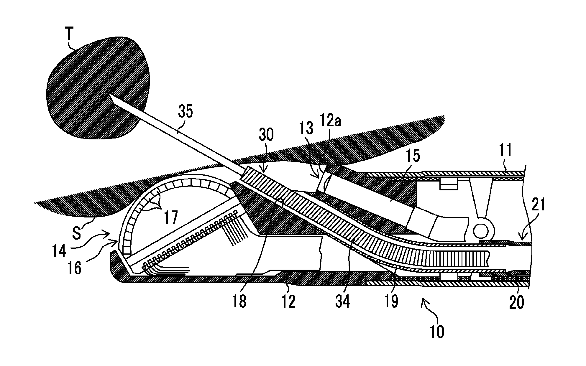
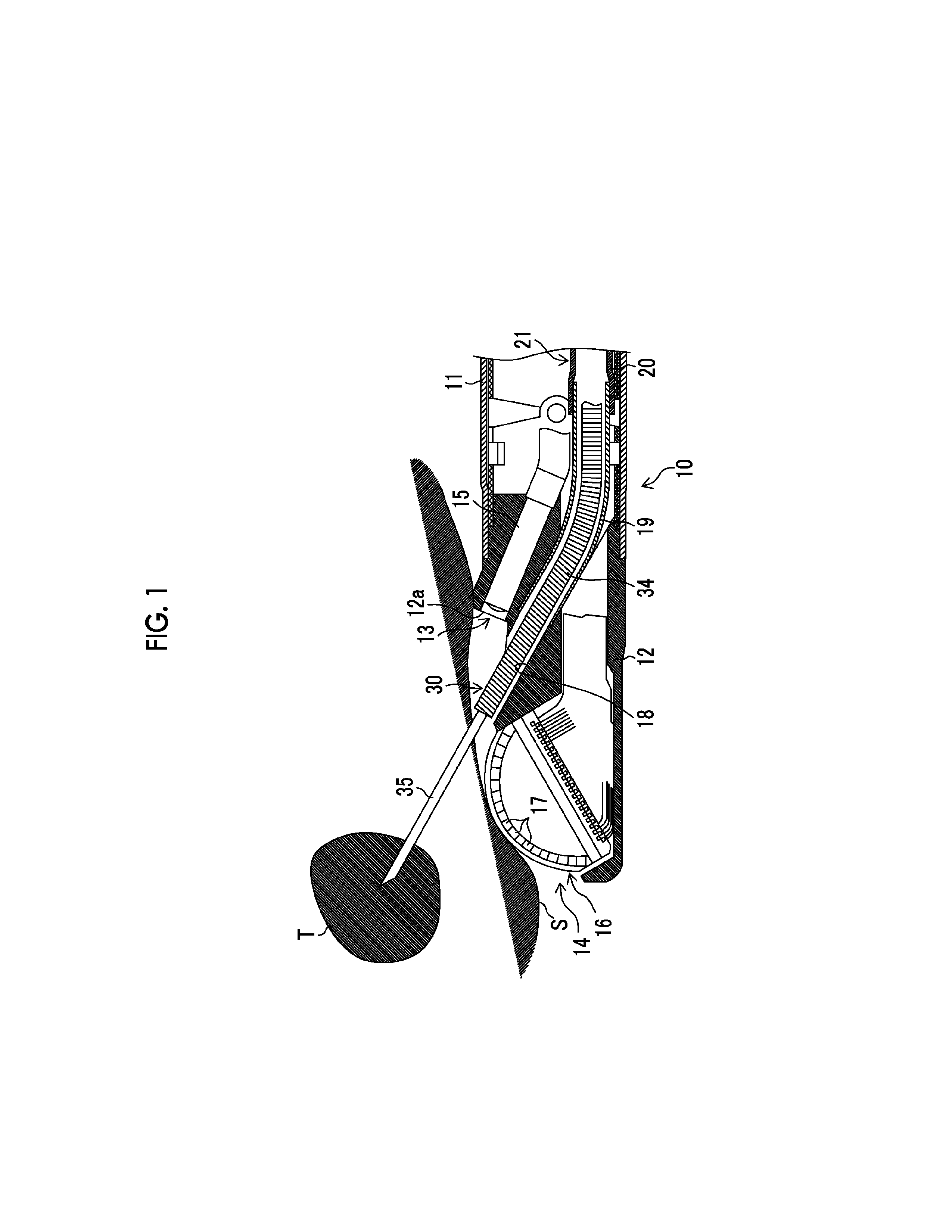
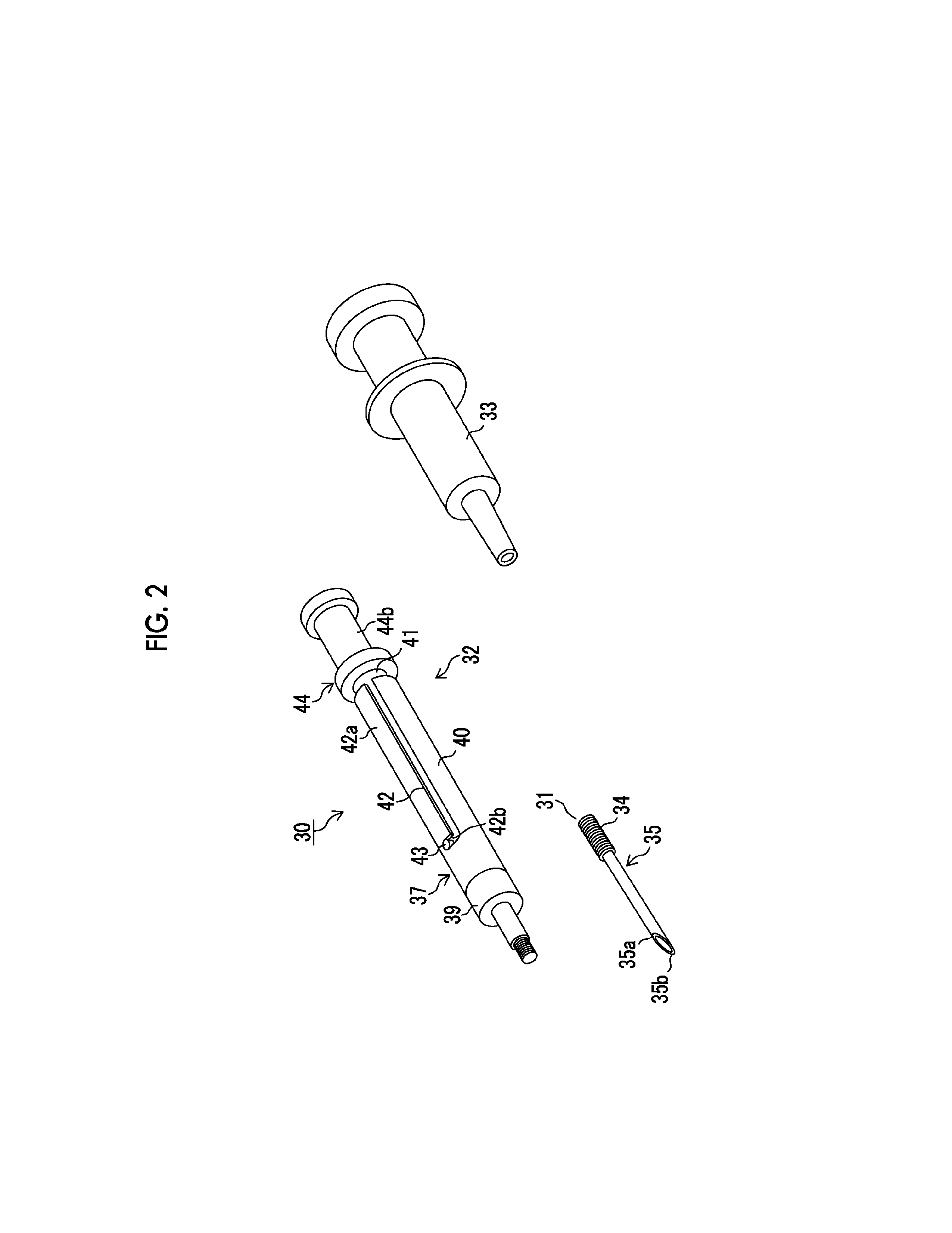
[0085]The base end portion of the sheath member 34 is provided to be fixedly attached to the connecting member 39 and the connecting member 39 is connected to the casing 40 constituting the first operating means 37. The casing 40 is constituted by a cylindrical member having a predetermined length, and in the inside thereof, the slider 41 is inserted so as to be able to slide in the axial direction of the casing 40. Similarly to the first embodiment, the slider 41 is hollow and the base end portion of the puncture pipe body 35 is fixedly attached to the inside thereof. Therefore, if the slider 41 is operated to be pushed and pulled, the needle tip 35b of the leading end of the puncture pipe body 35 moves in and out from the leading end of the sheath member 34.
[0086]Further, the guide hole 42 having a predetermined length is provided in the axial direction in the peripheral body portion of the casing 40 and the pin 43 which is inserted into the guide hole 42 is attached to the slider...
second embodiment
[0109]The details of the configurations of the locking groove 52 and the needle housing hole 54 will be described later and a form when disposing the tissue harvesting apparatus 30 after use is shown in FIG. 16. When disposing the tissue harvesting apparatus 30, as shown in FIG. 16, the sheath member 34 (and the catheter 31 constituted by the puncture pipe body 35 inserted and arranged in the inside of the sheath member 34, and the cutter pipe body 36 in the second embodiment) extending toward the front from the connecting member 39 (refer to FIGS. 2, 4, 7, and 9) of the leading end of the operating unit 32 is curved toward the rear (the base end side) in the vicinity of the base end portion. Then, the sheath member 34 curved in the vicinity of the base end portion is fitted into any one of the locking grooves 52, 52, and 52 formed in a plurality, whereby the sheath member 34 is locked by the locking groove 52. Then, an extra length portion of the sheath member 34, which becomes pos...
third embodiment
[0128]the needle housing hole 54 provided with the come off prevention means is shown in FIG. 20. FIG. 20 is a cross-sectional view in which the needle housing hole 54 is cut in a plane in the insertion direction of the puncture pipe body 35 (a depth direction). As shown in the same drawing, as the come off prevention means, a rubber member 70 (an elastic member) in which a hole housing the needle tip 35b of the puncture pipe body 35 is drilled by the needle tip 35b when housing the needle tip 35b of the puncture pipe body 35 in the needle housing hole 54 is provided in the inside of the needle housing hole 54.
[0129]The needle housing hole 54 is formed as a hole having an arbitrary shape such as a columnar shape or a rectangular parallelepiped shape, for example, and the rubber member 70 is formed in a shape approximately matching to the shape of the needle housing hole 54 and fitted so as to fill up the entire inside of the needle housing hole 54 almost without a gap. In addition, ...
PUM
 Abstract
Description
Claims
Application Information
 - R&D
- Intellectual Property
- Life Sciences
- Materials
- Tech Scout
- Unparalleled Data Quality
- Higher Quality Content
- 60% Fewer Hallucinations
Browse by: Latest US Patents, China's latest patents, Technical Efficacy Thesaurus, Application Domain, Technology Topic, Popular Technical Reports.
© 2025 PatSnap. All rights reserved.Legal|Privacy policy|Modern Slavery Act Transparency Statement|Sitemap|About US| Contact US: help@patsnap.com