
Drive system and method for operating such a drive system

Active Publication Date: 2013-07-18
ELFA NEW ENERGY VEHICLES EPOWERTRAIN SYST LTD +2
View PDF18 Cites 11 Cited by
  • Summary
  • Abstract
  • Description
  • Claims
  • Application Information

AI Technical Summary

Benefits of technology

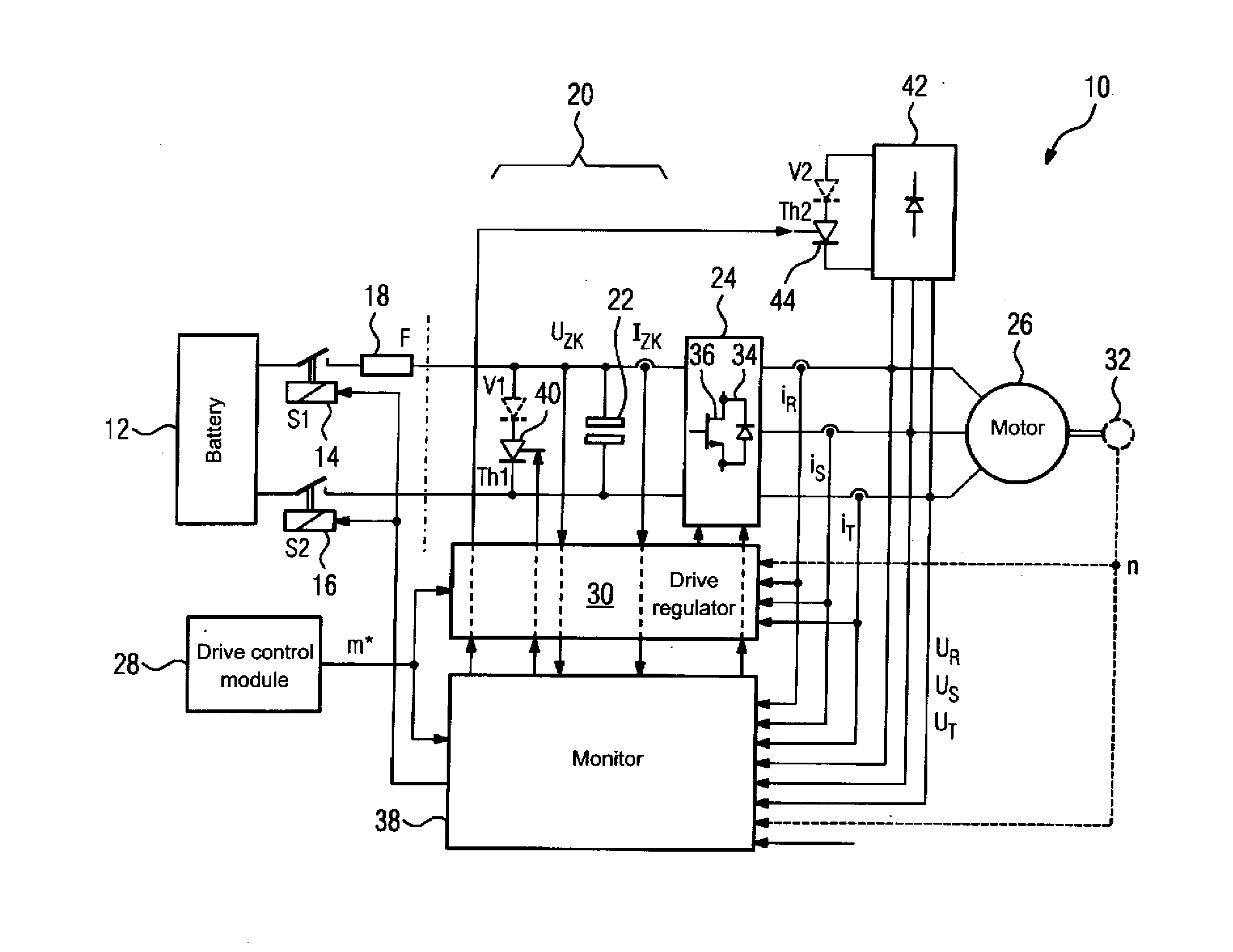
The invention is a control system for a drive system, which prevents damage to the system from overvoltages or short circuits. It includes a monitoring device that compares the voltage and current in the system and activates a thyristor if a certain threshold is exceeded. The system also has a fuse that can isolate the inverter from the battery to protect the thyristor. The monitoring device can activate additional thyristors or transistors to bring about an armature short circuit and extinguish the previously activated thyristor. The technical effect of this invention is to safeguard the efficiency and reliability of the drive system.

Problems solved by technology

However, the field weakening current can no longer be maintained in the event of a malfunction.
However the probability that an IGBT module or an activation circuit provided for its activation will fail in such a manner that an armature short circuit is no longer possible is relatively high or at least so high that it is not possible to meet safety requirements in this manner.
If for example neither the lower nor the upper transistors can be activated, the problem arises that normally the electromotive force (EMF) of the motor would increase by certain factors in relation to the nominal voltage at high speeds after elimination of the demagnetization current and with the motor connectors open.
This is prevented by clamping the stator voltage across the freewheeling diodes to the battery voltage but this produces the exceptional situation of a high recovery current into the battery, generating a high, impermissible braking torque.
This can cause the destruction of the inverter and / or of the motor as well as arcing with fire as a result and can eliminate the safe electrical isolation of inverter and motor.

Method used


Image

  • Drive system and method for operating such a drive system
  • Drive system and method for operating such a drive system
  • Drive system and method for operating such a drive system

Examples


Embodiment Construction

[0031]Throughout all the figures, same or corresponding elements may generally be indicated by same reference numerals. These depicted embodiments are to be understood as illustrative of the invention and not as limiting in any way. It should also be understood that the figures are not necessarily to scale and that the embodiments are sometimes illustrated by graphic symbols, phantom lines, diagrammatic representations and fragmentary views. In certain instances, details which are not necessary for an understanding of the present invention or which render other details difficult to perceive may have been omitted.

[0032]Turning now to the drawing, and in particular to FIG. 1, there is shown a simplified schematic diagram a drive system 10 for an electric vehicle (not shown). The drive system 10 includes a battery 12, in particular a high-voltage battery, which is connected by way of a first and second switch 14, 16 and a fuse 18 to an intermediate circuit 20 with an intermediate circu...


PUM


Abstract

A drive system for an electric motor includes a connection for a battery, and an inverter having an input side connected to an intermediate circuit and an output side having a connection for an electric motor. The intermediate circuit includes a first thyristor connected in parallel with an intermediate circuit capacitance. The drive system may also include a rectifier having an input side connected at the output side of the inverter in parallel with the electric motor, and a second thyristor connected an output side of the rectifier. The first / second thyristor are configured to be activated by a monitor incorporated in or assigned to the drive system. In the event of a malfunction, the input and / or output side of the inverter can be electrically isolated to allow a multiply redundant armature short circuit.

Description

CROSS-REFERENCES TO RELATED APPLICATIONS[0001]This application claims the priority of European Patent Application EP11174344, filed Jul. 18, 2011, pursuant to 35 U.S.C. 119(a)-(d), the content of which is incorporated herein by reference in its entirety as if fully set forth herein.BACKGROUND OF THE INVENTION[0002]The present invention relates to a drive system and a method for operating such a drive system, in particular for an electric vehicle.[0003]The following discussion of related art is provided to assist the reader in understanding the advantages of the invention, and is not to be construed as an admission that this related art is prior art to this invention.[0004]An electric vehicle is driven by way of a battery carried by said vehicle, a drive regulator, an inverter and an electric motor—hereafter referred to simply as a motor. The drive system here contains at least the drive regulator and the inverter. If a battery and motor are connected, these are also part of the driv...

Claims


Application Information

Patent Timeline
IPC IPC(8): H02P3/08
CPCH02P3/22B60L7/14B60L11/1803Y02T10/642H02P3/08Y02T10/7005B60L3/0076B60L50/51Y02T10/64Y02T10/70
Inventor KOPKEN, HANS-GEORGSCHWESIG, GUNTER
Owner ELFA NEW ENERGY VEHICLES EPOWERTRAIN SYST LTD
Learn More