
Bearing structure

Inactive Publication Date: 2013-07-11
SHOWA CORP
View PDF4 Cites 6 Cited by
  • Summary
  • Abstract
  • Description
  • Claims
  • Application Information

AI Technical Summary

Benefits of technology

The present invention provides a bearing structure that prevents abnormal noise and rusting, prevents muddy water from entering the front side of the bearing, and allows muddy water in one side of the bearing to be discharged to the outside in a satisfactory manner. This is achieved by using a cover member that covers the rib, which prevents muddy water from splashing up and striking the rib directly.

Problems solved by technology

S53-13147 and Japanese Patent Application Publication No. 2008-208903, since the lip and shaft member make contact, then there is a risk of abnormal noise occurring with the rotation of the shaft member.
Furthermore, if the front end of the lip becomes worn, then a gap is formed between the lip and the shaft member, and there is a risk of water infiltrating through this gap.
Moreover, since the lip is formed with a small thickness, then there is a risk of the lip deforming due to the water which splashes up from the front wheels, leading to infiltration of water.
Moreover, in the technology according to Japanese Unexamined Utility Model Application Publication No 555-168428, the groove in the shaft member becomes rusted due to the water, the depth and width of the groove decrease, and hence the gap between the groove and the projection becomes smaller, leading to a risk of abnormal noise.
H7-101256, since the inner ring and the rubber mount are bonded by cure adhesion, surface treatment of the inner ring is not possible.
Therefore, rusting occurs on the exposed portions of the inner ring, and there is a risk of contact between the shaft member and portions of the inner ring that have expanded due to the rust.
H1-119921, since the surface of the inner ring makes contact with the outside air, rusting occurs, and if this rust progresses to the interface between the lip and the inner ring, then the lip detaches from the inner ring, the gap becomes large, and there is a risk of infiltration of water.
H1-119921, when the vehicle travels through puddles, and so on, and the bearing is immersed in water, then water collects between the inner ring and the outer ring, and a problem arises in that this water cannot be readily discharged to the outside.

Method used


Image

  • Bearing structure
  • Bearing structure
  • Bearing structure

Examples


modification examples

[0092]One embodiment of the present invention was described above, but the present invention is not limited to this and can be modified as described below, for instance.

[0093]In the embodiment described above, a composition is described in which the constant-velocity joint 1 has a tripod configuration, but the form of the joint may be modified suitably. For example, the joint may be changed to a double-offset joint, a cross groove joint, or a fixed joint. Of these, if the constant-velocity joint 1 is a cross groove joint, then the sliding grooves of the outer ring are inclined in the round circumferential direction with respect to the axis line (axial direction), and the balls (sliding elements) of the trunnion assembly slide along the sliding grooves, in other words, in an oblique direction with respect to the axis line.

[0094]In the embodiment described above, a composition is explained in which drive force is input to the outer ring 10, but it is also possible to adopt a compositi...


PUM


Abstract

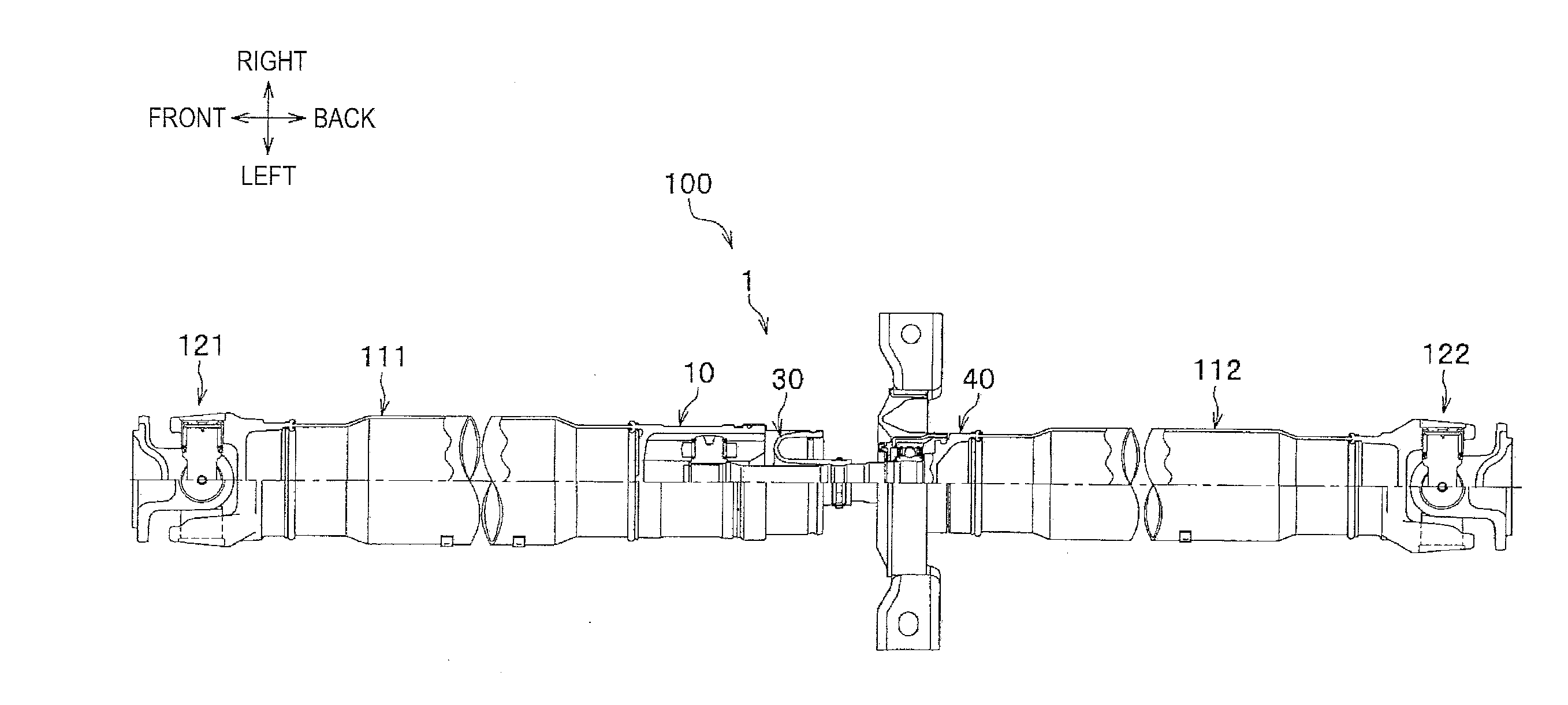
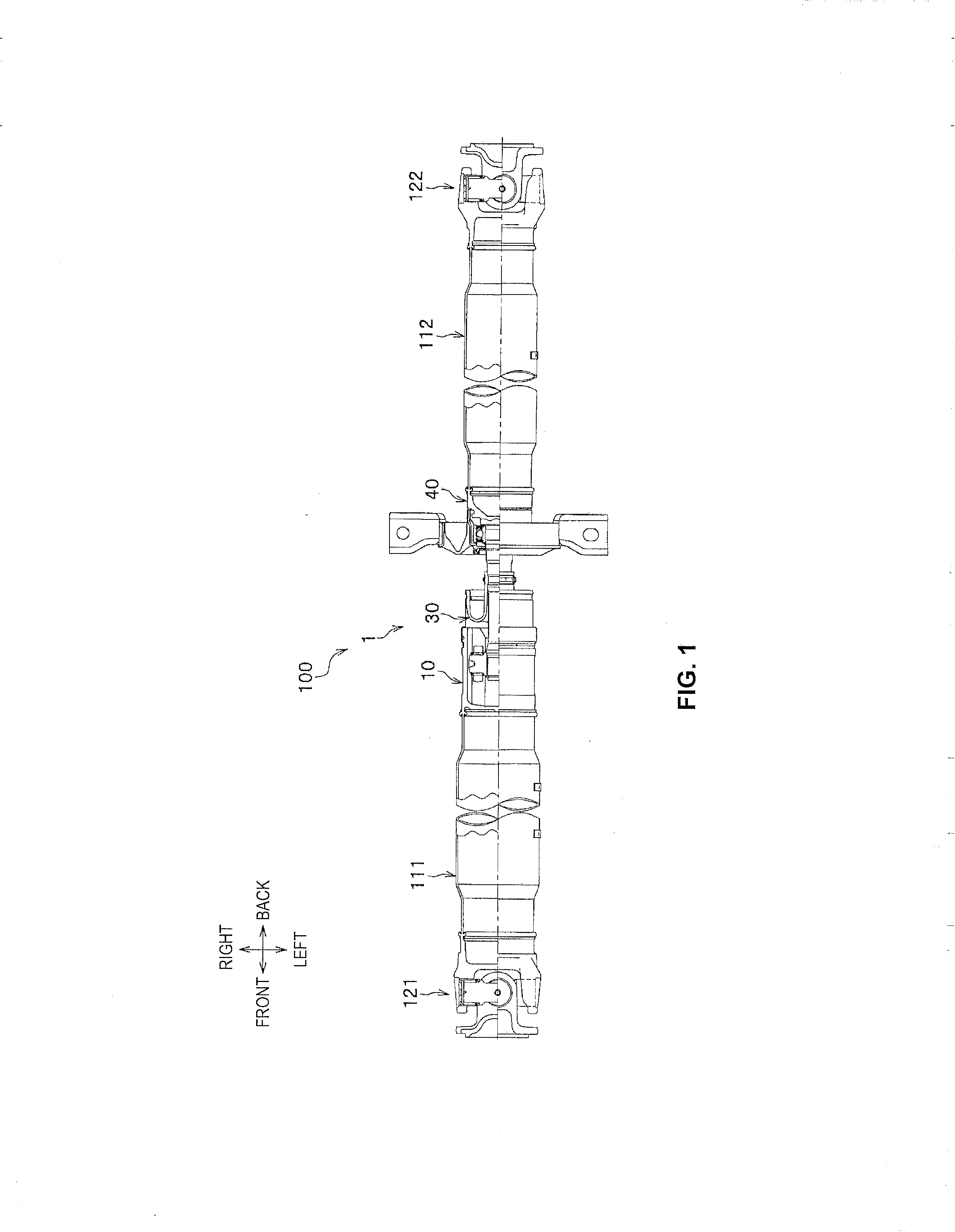
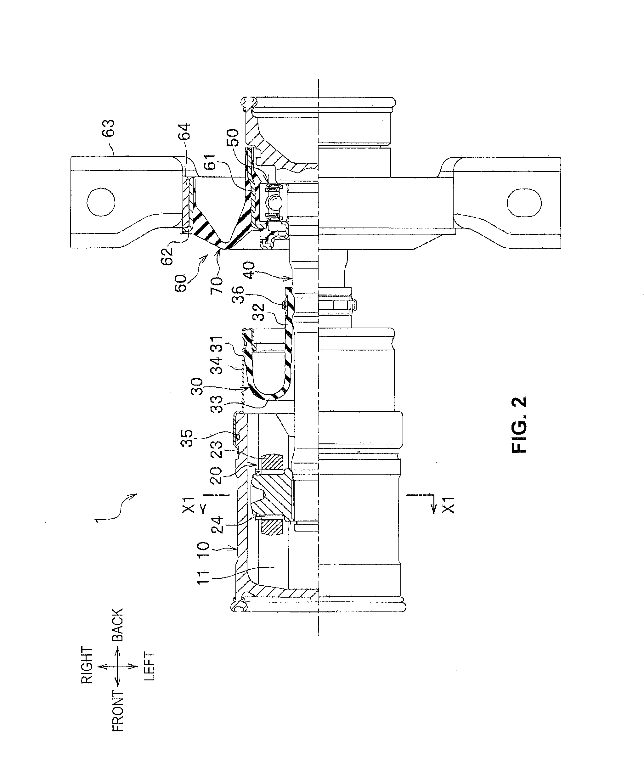
A bearing structure comprises a shaft member, a bearing, an inner ring, a ring-shaped mount which is made of an elastic material, is fixed to a vehicle body and encloses the inner ring, and a dust cover which is fixed to the bearing member and rotates in unison with the bearing member, the bearing member being supported rotatably on the vehicle body via the bearing. The mount includes, on a front side, a rib facing inward in a radial direction and extending in a circumferential direction so as to seal off a first gap formed between the shaft member and the inner ring. A second gap is formed between an inner radial end of the rib and the shaft member. The dust cover covers the rib and the second gap on the front side of the rib. A cutout is formed in a lower vertical portion of the rib.

Description

CROSS-REFERENCE TO RELATED PATENT APPLICATIONS[0001]This application claims the benefit of Japanese Patent Application No. 2012-002555, filed Jan. 10, 2012, which is incorporated by reference herein.FIELD OF THE INVENTION[0002]The present invention relates to a bearing structure of a bearing which rotatably supports a propeller shaft of a vehicle.BACKGROUND OF THE INVENTION[0003]In general, in a rear wheel drive or four-wheel drive four-wheel vehicle, motive power from a transmission device is transmitted to a final reduction gear device provided in the center of left and right rear wheels, via a propeller shaft which extends in a front / rear direction in the center of the vehicle width direction. Here, a critical speed of the propeller shaft needs to be set higher than a practical rotational speed range, and therefore the propeller shaft is divided into appropriate lengths.[0004]For example, if the propeller shaft is divided into two pieces, then as shown in FIG. 8, the propeller sh...

Claims


Application Information

Patent Timeline
IPC IPC(8): F16C3/02
CPCF16C3/02F16C2326/06B60K17/24F16F1/38F16C19/06F16C27/066F16C33/805
Inventor HATOGAI, ATARU
Owner SHOWA CORP
Learn More