
Apparatus and method for cooling a substantially closed space

a substantially closed space and apparatus technology, applied in the direction of energy-efficient heating/cooling, fluid pressure control, heating types, etc., can solve the problems of inability to adequately handle such situations, inability to provide adequate system performance, and inability to achieve energy-efficiency as obtained in operation

Inactive Publication Date: 2013-07-11
DEERNS RAADGEVENDE INGS
View PDF6 Cites 25 Cited by
  • Summary
  • Abstract
  • Description
  • Claims
  • Application Information

AI Technical Summary

Benefits of technology

The patent describes an apparatus for cooling a closed space using multiple units. The units operate in parallel and are controlled by a master controller. The master controller determines the maximum operation of each unit based on the sensor signals from the other units. This ensures that even if one unit malfunctions, the other units can still operate efficiently. The cooling units draw air from the closed space and provide cooled air back to the space. The system performance and load distribution can be improved by redundant operation and efficient energy consumption. The apparatus is designed to provide stable and reliable control and to improve system performance and load distribution.

Problems solved by technology

A problem of such known cooling is that energy efficiency as obtained in operation may be sub-optimal.
From a system perspective, the individual control may not be able to adequately handle such situations and may not be able to provide adequate system performance.
Such below adequate performance may result in unnecessary consumption of energy and / or result in the cooling system not achieving a required performance.
Such changes may occur as a result of many causes, such as by addition, removal or taking out of service of parts or components or data processing equipment, pressure, air flow and / or temperature differences by opening or closing of a door, changes in a dissipation or dissipation distribution of the datacenter, changes in environmental temperature, errors by maintenance staff (such as forgetting to close an opening in a computer rack after removal of a unit from the rack, forgetting to close a door, a window, service opening, removal or placement of data processing equipment, or others).
This may result in low performance and therefore in unnecessary consumption of energy and / or the cooling system not achieving a required performance.
Again, this may result in low performance and therefore in unnecessary consumption of energy and / or the cooling system not achieving a required performance.

Method used


Image

  • Apparatus and method for cooling a substantially closed space
  • Apparatus and method for cooling a substantially closed space

Examples


Embodiment Construction

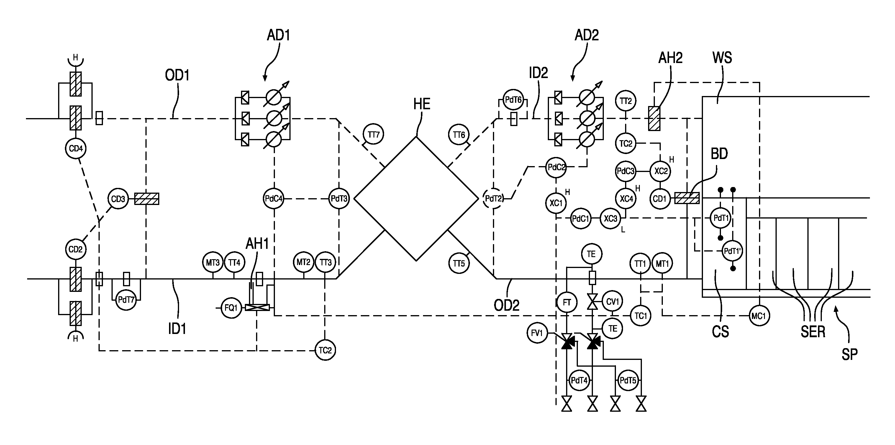
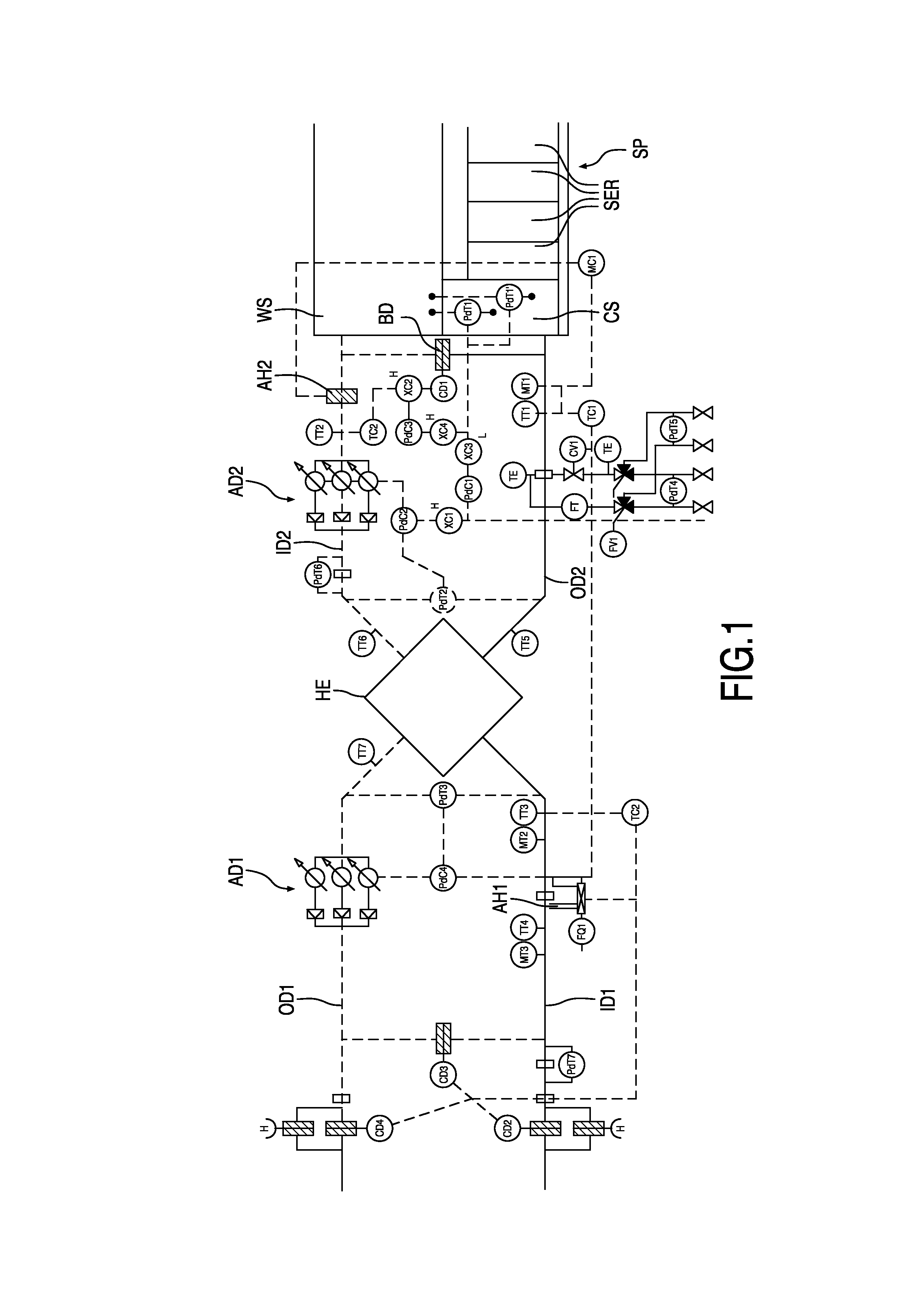
[0028]FIG. 1 depicts a schematic view of an apparatus for cooling a substantially closed space, in this embodiment a datacenter. The apparatus comprises a (cooling) unit comprising a heat exchanger HE, in this embodiment a plate heat exchanger, although other heat exchangers, such as a heat exchanger comprises a rotatable thermal wheel, may be applied alternatively. The unit comprises a first set of ducts formed by primary inlet duct ID1 and primary outlet duct OD1, both being connected to an outdoor environment. A primary air displacement device AD1, such as one or a plurality of ventilators (the FIG. 1 embodiment depicts 3 parallel ventilators), is provided in one of the primary inlet and outlet ducts. By operation of the primary air displacement device, outside air is led via the primary inlet duct, through the heat exchanger, to the primary outlet duct. Likewise, the unit comprises a second set of ducts formed by secondary inlet duct ID2 and secondary outlet duct OD2, both being...


PUM


Abstract

An apparatus for cooling a substantially closed space with recirculation air having at least one cooling unit which includes a heat exchanger with a primary set of ducts and a secondary set of ducts, each set of ducts having an in- and outlet. The unit includes a controller to control an operation of the unit, and a sensor to provide a sensor signal representative of a parameter of the unit. The controller is arranged to derive a control signal from the sensor signal, whereby the unit includes a control signal output for outputting the control signal to another unit and a control signal input for receiving a control signal from another unit, the controller being arranged to control the operation of the unit in response to the control signal and the control signal from another unit as received at the control signal input.

Description

CROSS-REFERENCE TO RELATED APPLICATIONS[0001]This application is the National Stage of International Application No. PCT / NL2011 / 050535, filed Jul. 22, 2011, which claims the benefit of Netherlands Application No. 2005138, filed Jul. 23, 2010, the contents of which is incorporated by reference herein.FIELD OF THE INVENTION[0002]The invention relates to an apparatus and method for cooling a substantially closed space, in particular a data centre, with recirculation air, as well as to such a datacenter. Furthermore, the invention relates to such datacenter.BACKGROUND OF THE INVENTION[0003]WO2009 / 108043 discloses a cooling of a datacenter. A first air stream is guided through data processing equipment of the datacenter. The air stream is guided to a plate heat exchanger where it is cooled by a second air stream comprising ambient air. Then, the first air stream is guided back to the datacenter for cooling of the data processing equipment. The second air stream a separated from the first...

Claims


Application Information

Patent Timeline
Patent Type & Authority Applications(United States)
IPC IPC(8): H05K7/20F24F3/14
CPCF24F12/006F24F2012/007H05K7/20745H05K7/20836Y02B30/563H05K7/20145H05K7/202H05K7/20209F24F3/14Y02B30/56
Inventor HUNDERTMARK, THOMAS FERDINAND WILLEM
Owner DEERNS RAADGEVENDE INGS
Learn More