Liquid storage device

a technology of liquid storage and liquid storage chamber, which is applied in the direction of fluid pressure control, process and machine control, instruments, etc., can solve the problems of tank damage and affect the whole manufacturing process

Active Publication Date: 2013-07-11
BEIJING SEVENSTAR ELECTRONICS CO LTD
View PDF4 Cites 3 Cited by
  • Summary
  • Abstract
  • Description
  • Claims
  • Application Information

AI Technical Summary

Benefits of technology

The invention provides a liquid storage device that prevents chemical liquids from being damaged and allows for smooth discharge. This is achieved through the use of a gas compensating tube that quickly supplies protective gas into the tank, replacing the need for a liquid seal container.

Problems solved by technology

However, since the pressure relief valve and the vacuum breaking valve are interlock mechanisms and easy to lose mechanical sensitivity after being used for a certain time, the pressure in the storage tank may become unstable which may result in the damage of the tank and affect the whole manufacturing process.

Method used


Image

  • Liquid storage device
  • Liquid storage device
  • Liquid storage device

Examples


first embodiment

[0026]As shown in FIG. 3, which is a schematic diagram of the liquid storage device according to the present invention, the liquid storage device 300 comprises a liquid storage tank 310, a liquid intake tube 320, a liquid discharge tube 330, a gas discharge tube 350, and a gas compensating tube 360; the liquid intake tube 320, the liquid discharge tube 330, the gas discharge tube 350 and the gas compensating tube 360 are all connected with the liquid storage tank 310. The shape of the liquid storage tank 310 can be cylinder, cone, cuboid, or another shape. In the present embodiment, the shape of the liquid storage tank 310 is a combination of cylinder and cone. The liquid intake tube 320, the gas discharge tube 350, and the gas compensating tube 360 are all connected to the top wall of the liquid storage tank 310; the liquid discharge tube 330 is connected to the bottom wall of the liquid storage tank 310.

[0027]A valve 321 is arranged on the liquid intake tube 320 for controlling th...

second embodiment

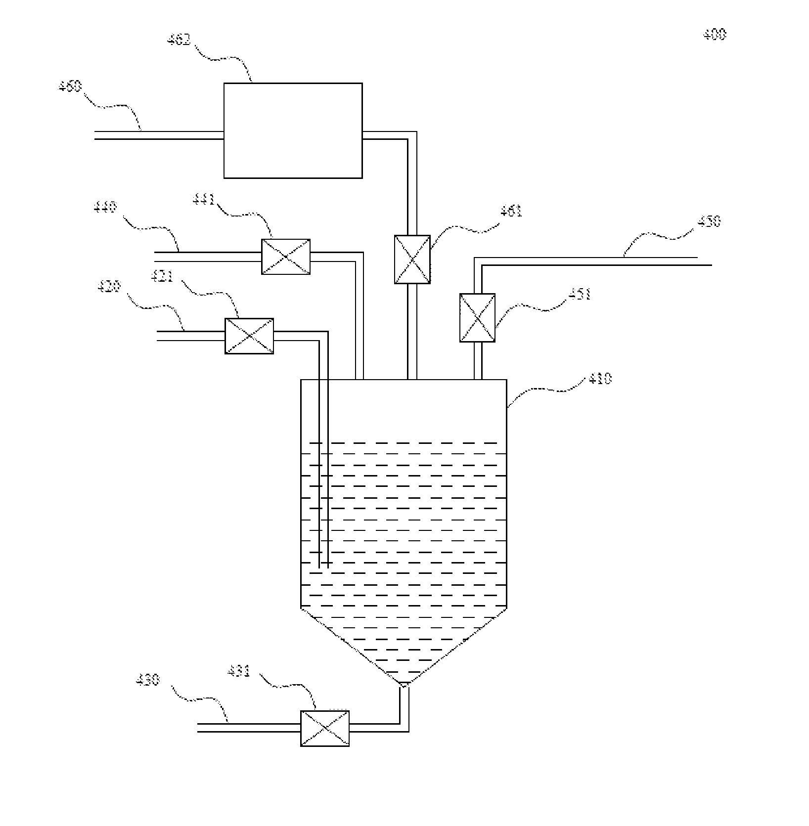
[0030]As shown in FIG. 4, the liquid storage device 400 according to the present invention comprises a liquid storage tank 410, a liquid intake tube 420, a liquid discharge tube 430, a gas intake tube 440, a gas discharge tube 450, and a gas compensating tube 460; the liquid intake tube 420, the liquid discharge tube 430, the gas intake tube 440, the gas discharge tube 450 and the gas compensating tube 460 are all connected with the liquid storage tank 410. The shape of the liquid storage tank 410 can be cylinder, cone, cuboid, or another shape. In the present embodiment, the shape of the liquid storage tank 410 is a combination of cylinder and cone. The liquid intake tube 420, the gas intake tube 440, the gas discharge tube 450, and the gas compensating tube 460 are all connected to the top wall of the liquid storage tank 410, and the liquid discharge tube 430 is connected to the bottom wall of the liquid storage tank 410.

[0031]A valve 421 is arranged on the liquid intake tube 420 ...


PUM


Abstract

The present invention provides a liquid storage device relates to the field of semiconductor manufacturing technology comprising: a liquid storage tank, a liquid intake tube, a liquid discharge tube and a gas discharge tube; the liquid intake tube, the liquid discharge tube and the gas discharge tube are all connected with the liquid storage tank; the liquid storage device also comprises a gas compensating tube connected with the liquid storage tank; the gas compensating tube comprises a differential pressure mechanism and a gas storage tank; one end of the differential pressure mechanism is connected with the liquid storage tank, and the other end is connected with the gas storage tank; the differential pressure mechanism is used for controlling the connection or disconnection between the liquid storage tank and the gas storage tank according to the pressure difference therebetween.

Description

CROSS-REFERENCE TO RELATED APPLICATION[0001]This application claims the priority benefit of China application serial no. 201110303518.9, filed Oct. 9, 2011. All disclosure of the China application is incorporated herein by reference.FIELD OF THE INVENTION[0002]The present invention relates to the field of semiconductor manufacturing technology, more particularly to a liquid storage device.BACKGROUND OF THE INVENTION[0003]Conventionally in the IC manufacturing process, different cleaning processes are required for the silicon wafers and during the cleaning processes, different chemical liquids may be used. For example, the chemical liquid ST250 is generally used in a cleaning apparatus for cleaning copper interconnections; the chemical liquids such as ammonia, oxyful, hydrofluoric acid, etc are generally used in a cleaning apparatus for cleaning polished wafers. In addition, the purity of the chemical liquids is highly required. In the cleaning processes, the different chemical liqui...

Claims


Application Information

Patent Timeline
IPC IPC(8): G05D16/16
CPCG05D16/00G05D16/16G05D16/103G05D16/028Y10T137/3127Y10T137/86324Y10T137/3115Y10T137/3118Y10T137/313
Inventor HE, JINQUNPEI, LIKUNWU, YIZAN, WEI
Owner BEIJING SEVENSTAR ELECTRONICS CO LTD
Why Eureka
Try Eureka