Battery cathode depolarization circuit

a cathode and battery technology, applied in the field of storage batteries, can solve problems such as damage to batteries, and achieve the effect of low internal electrical resistance of storage batteries and high charging ra

Inactive Publication Date: 2013-07-04
MCWHORTER EDWARD MILTON
View PDF1 Cites 3 Cited by
  • Summary
  • Abstract
  • Description
  • Claims
  • Application Information

AI Technical Summary

Benefits of technology

This patent aims to improve the performance of storage batteries by reducing their internal electrical resistance during periods of heavy discharge and high charging rates. This is achieved by transferring excessive hydrogen polarization charge at the battery electrode surfaces into an ionic capacitor. Other technical effects include decreasing the battery downtime relative to the useful operative discharging period, increasing the electrical vehicle operating range by charging the batteries at a rapid charging rate while the vehicle is in motion, and increasing the charging rate of transportation batteries while simultaneously reducing the heating rate and accumulated heat during the charging period.

Problems solved by technology

Heat is generated during the charging period and this heat is accumulative and can damage the battery during charging if not kept in check.

Method used


Image

  • Battery cathode depolarization circuit
  • Battery cathode depolarization circuit
  • Battery cathode depolarization circuit

Examples


Embodiment Construction

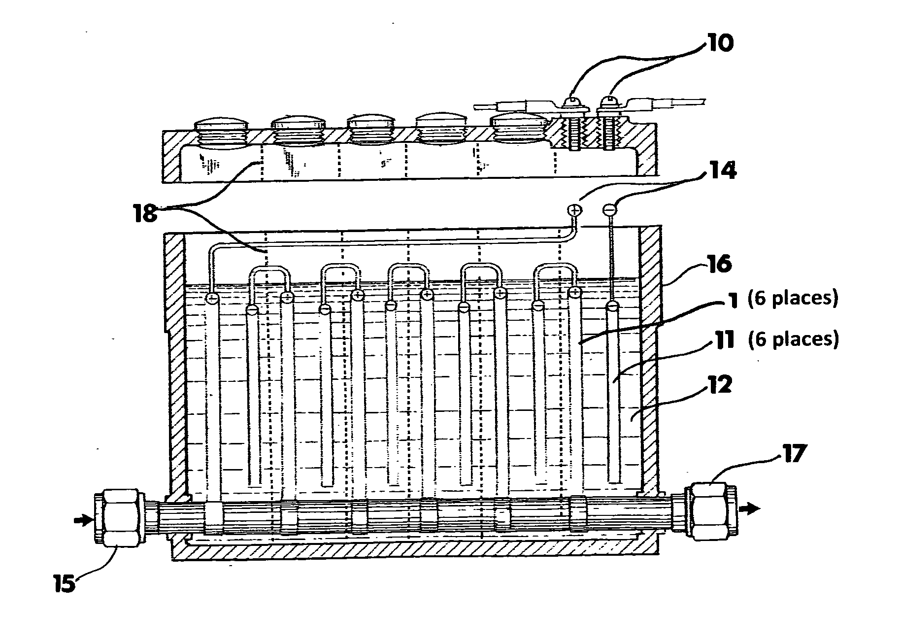
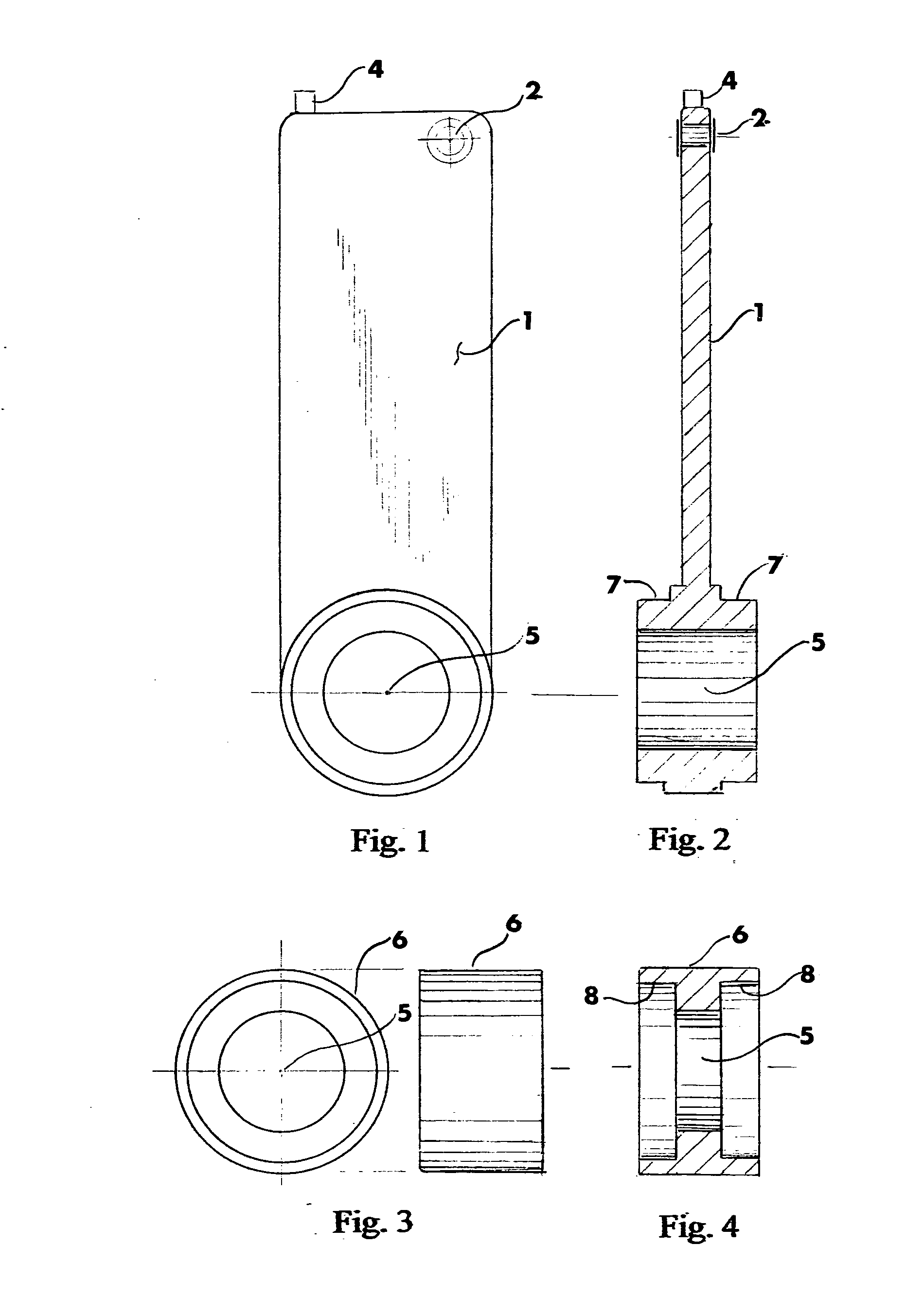
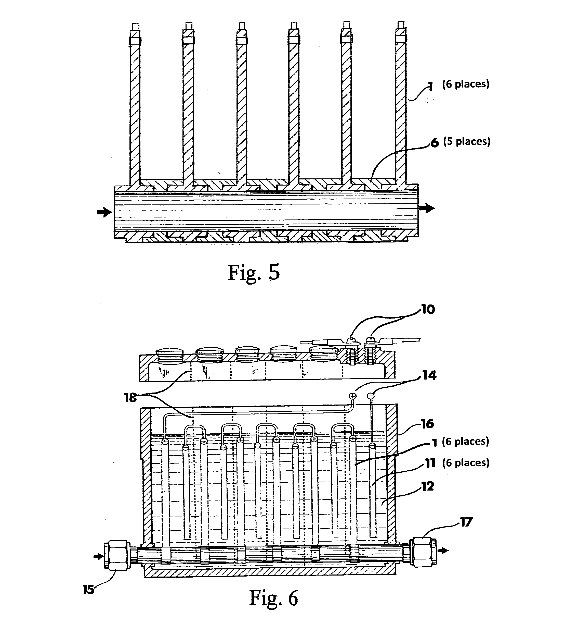
[0019]FIG. 1 is a frontal view of cathode 1. Cathode 1 is a metal cathode electrode. The type of metal used to construct cathode 1 determines the galvanic output of the assembled cell relative to the comparative oxidation states of selected anodes paired with cathode 1 metals immersed within a given battery electrolyte media.

[0020]The cathode 1 of FIG. 1 has a small hole 2 in the upper right hand corner for passage of an insulative supporting rod to steady the upper portion of cathode 1 within the cell compartment. A metal connector 4 is positioned in the upper left corner of cathode 1. Tubular metal conduit 5 is a short circular protruding passage formed at the lower end of cathode 1.

[0021]FIG. 2 is a side view of FIG. 1 shown in cross-section. Metal conduit 5 forms a cylindrical tubular passageway for the gaseous flow of a positive charged ionic class-2 conductor. The positive charged ionic class-2 conductor fluid is in electrical contact with the inner cylindrical surfaces of met...


PUM


Abstract

An electrical depolarization circuit is used to shorten the charging time of secondary cells by transferring a portion of the battery electrode cathode polarization charge into an ionic capacitor stream comprised of a gaseous ionic mixture of lower oxidative potential flowing within a tubular circuit passing through the battery electrolyte.

Description

CROSS REFERENCES[0001]Ref. 1 U.S. application Ser. No. 12 / 378,425 Rapid Charge Transportation Battery. Filed Feb. 17, 2009.[0002]Ref. 2 U.S. Pat. 6,831,825 Fuel Cell Ionic Capacitor. Application Ser. No. 10 / 457,702. Filed Jun. 10, 2003.[0003]Ref.3 U.S. Pat. No. 8,071,041 Potassium Electric Generator and Chemical Synthesizer. Application No. 12 / 005,093. Filed Dec. 26, 2007.CLAIM OF PRIORITY[0004]The present application is a continuation-in-part of Ref. 1.BACKGROUND OF THE INVENTION[0005]The invention is a storage battery comprised of a plurality of rechargeable secondary cells having their anode and cathode electrodes interconnected by three types of electrical conductor circuits. The metal electrodes are connected in electrical series by class-1 wire conductors. The metal electrodes being immersed in an electrolyte are also interconnected by electrolytic class-2 conduction through the liquid medium while exchanges of oxidation reactions are alternately occurring during battery disch...

Claims


Application Information

Patent Timeline
Patent Type & Authority Applications(United States)
IPC IPC(8): H02J7/00
CPCH01M10/4264H01M10/44Y02E60/10
Inventor MCWHORTER, EDWARD MILTON
Owner MCWHORTER EDWARD MILTON
Why Eureka
Try Eureka