
Receiving device, screen frame transmission system and method

a transmission system and screen frame technology, applied in the field of receiving devices and screen frame transmission systems and methods, can solve the problems of increasing the delay between the transmission of the screen frame on the transmitting end and the display of the screen frame on the receiving end, hindering the user from controlling the remote host with ease, etc., to achieve smoother video playback, reduce the delay for displaying the screen, and reduce the delay effect of latency delay

Inactive Publication Date: 2013-06-27
AWIND INC
View PDF5 Cites 15 Cited by
  • Summary
  • Abstract
  • Description
  • Claims
  • Application Information

AI Technical Summary

Benefits of technology

The present invention is a device that allows users to switch between an operating mode and a video mode. During the operating mode, the device reduces the delay in showing the screen by buffering less screen frame data, providing a better user experience. During the video mode, the device buffers more screen frame data to enable smoother playback of the video.

Problems solved by technology

However, when the receiving end buffers the screen frame data, the latency delay between the transmission of the screen frame on the transmitting end and the display of the screen frame on the receiving end would increase.
For example, when a user hit a keyboard remotely, it may take 2 to 3 seconds before the displaying screen shows the response, which hinders the user from controlling the remote host with ease.

Method used


Image

  • Receiving device, screen frame transmission system and method
  • Receiving device, screen frame transmission system and method
  • Receiving device, screen frame transmission system and method

Examples


Embodiment Construction

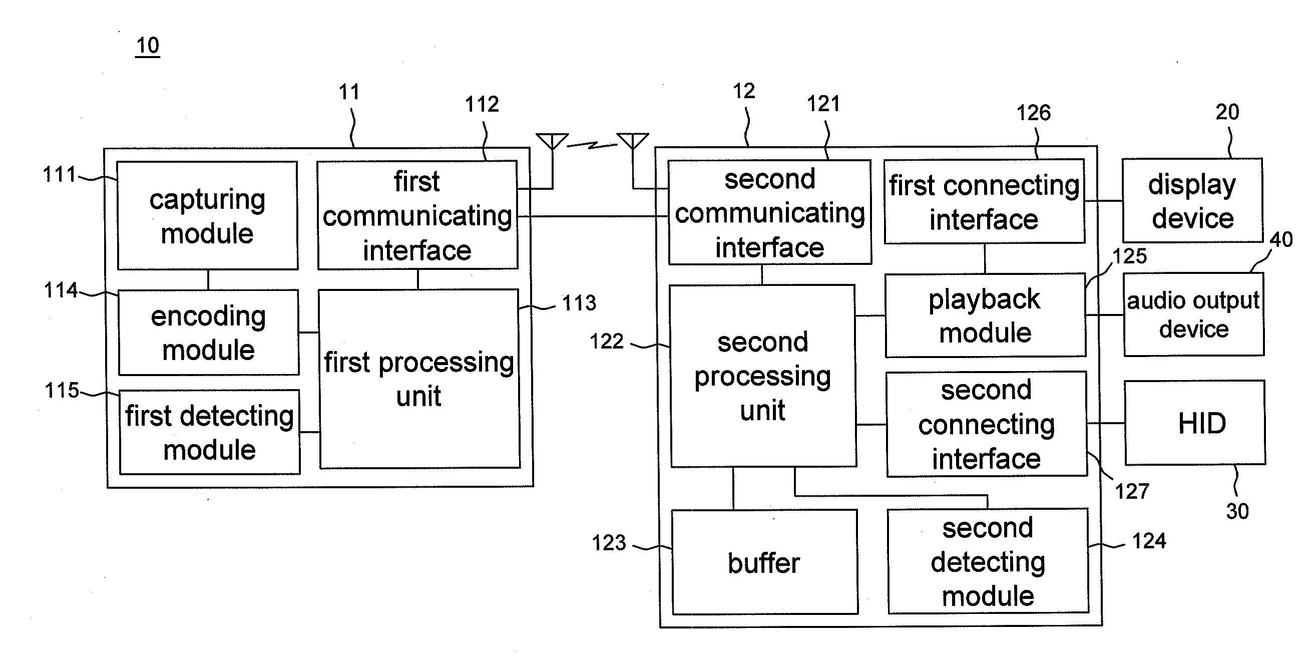
[0015]Referring to FIG. 1, there is illustrated a screen frame transmission system 10 according to an embodiment which includes a transmitting device 11 and a receiving device 12. The transmitting device 11 includes a capturing module 111, a first communicating interface 112 and a first processing unit 113. The capturing module 111 is for capturing a screen frame data; e.g. the capturing module 111 may rely on the operating system to obtain the lossless screen frame data by a software program. The first communicating interface 112 is for converting the captured screen frame data and the audio data into a communicating signal and transmitting the communicating signal. The first processing unit 113 is electrically connected with the capturing module 111 and the first communicating interface 112 for processing the captured screen frame data and the audio data from the capturing module 111 and transmitting the screen frame data and the audio data through the first communicating interfac...


PUM


Abstract

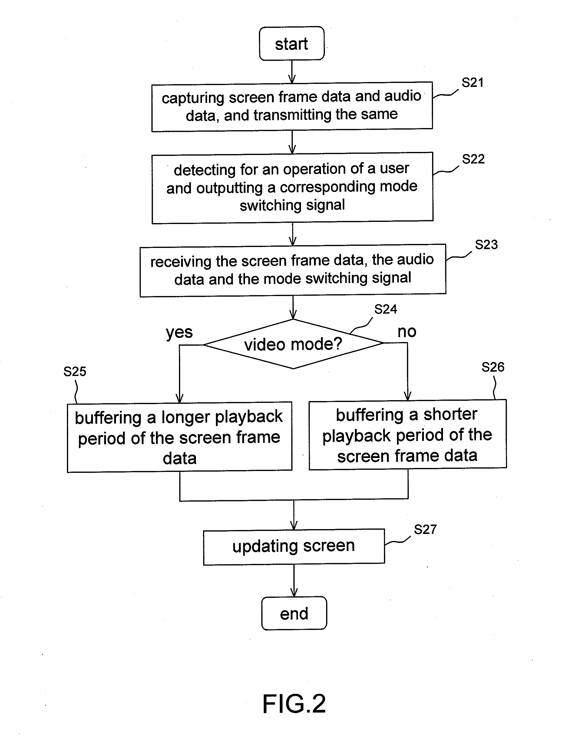
A screen frame transmission method includes a transmitting end capturing screen frame data and audio data and transmitting the same to a receiving end, and detecting for a user's operation and outputting a mode switching signal; a receiving end buffering the screen frame data transmitted by the transmitting end, and according to the mode switching signal, switching to the operating mode or the video mode, wherein during the video mode, a longer playback period of the screen frame data are buffered, and during the operating mode, a shorter playback period of the screen frame data are buffered. According to the aforementioned method, during the video mode, the video may be played back smoothly and the video and the audio are synchronized; during the operating mode, a low latency delay control experience may be provided. A receiving device and screen frame transmission system realizing the above method are also disclosed.

Description

REFERENCE TO RELATED APPLICATION[0001]This is a continuation-in-part of application Ser. No. 12 / 973,532, filed Dec. 20, 2010.BACKGROUND OF THE INVENTION[0002]1. Field of the Invention[0003]The present invention relates to a receiving device, screen frame transmission system and method, and more particularly to a receiving device, screen frame transmission system and method capable of adjusting latency delay according to human interface device (HID) status.[0004]2. Description of the Prior Art[0005]Screen sharing is an important application of information technology. Examples of screen sharing include remote desktop control, or wirelessly connecting a computer with a projector for a presentation and so on. In the past, screen sharing technology is suitable only for the transmission of more static contents owing to lower frame rate, but with the continuous progress of computer performance, image compression technology and wireless network bandwidth, the screen sharing technology now a...

Claims


Application Information

Patent Timeline
Patent Type & Authority Applications(United States)
IPC IPC(8): H04L29/06
CPCG06F3/1454H04L67/025H04N21/44222H04N21/4384H04N21/44004H04L65/608G09G2350/00G09G2354/00G09G2360/18
Inventor CHANG, KUO-LUNGWANG, HSING-YUNGCHOU, KUAN-YUHUNG, MENG-CHUNGFAN, CHIN-JUNGCHEN, LI-GER
Owner AWIND INC
Learn More