
Pattern transfer apparatuses and methods for controlling the same

a pattern transfer and pattern technology, applied in the field of pattern transfer apparatuses and methods for controlling the same, can solve the problems of increasing the process time for patterning, requiring a relatively long processing time, and reducing the productivity of the photolithography process, so as to improve economic feasibility, facilitate pattern transfer, and analyze the cause of the defect with relative ease

Inactive Publication Date: 2013-06-20
SAMSUNG ELECTRONICS CO LTD
View PDF5 Cites 4 Cited by
  • Summary
  • Abstract
  • Description
  • Claims
  • Application Information

AI Technical Summary

Benefits of technology

The patent describes a method for checking the position of defects on a substrate and transferring patterns to them simultaneously using a microscope integrated with a stamp. This approach allows for faster and more efficient pattern transfer, resulting in more accurate and precise patterns. Additionally, the stamp can be easily removed and replaced with different patterns, improving economic feasibility. The pattern size can also be adjusted based on the microscope's magnification, making pattern transfer easier. Furthermore, the defect position can be easily marked, making it easier to analyze the cause of the defect.

Problems solved by technology

However, whenever a pattern is formed by using a photolithography process, exposure, development, etching and cleaning processes also should be performed, and this requires a relatively long processing time.
Further, because the photolithography process should be repeatedly performed, productivity of the photolithography process is relatively low.
Because the checking of the defect position of the substrate using the microscope is performed independently from the transfer of the micro pattern of the stamp, an error or a difference between the defect position of the substrate checked by the microscope and the transfer position of the micro pattern of the stamp is encountered, thereby increasing the process time for patterning.

Method used


Image

  • Pattern transfer apparatuses and methods for controlling the same
  • Pattern transfer apparatuses and methods for controlling the same
  • Pattern transfer apparatuses and methods for controlling the same

Examples


Embodiment Construction

[0053]Example embodiments will now be described more fully with reference to the accompanying drawings. Example embodiments may, however, be embodied in many different forms and should not be construed as being limited to the embodiments set forth herein; rather, these embodiments are provided so that this disclosure will be thorough and complete, and will fully convey the concept of example embodiments to those of ordinary skill in the art. In the drawings, the thicknesses of layers and regions are exaggerated for clarity. Like reference numerals in the drawings denote like elements throughout, and thus their description will be omitted.

[0054]It will be understood that when an element is referred to as being “connected” or “coupled” to another element, it can be directly connected or coupled to the other element or intervening elements may be present. In contrast, when an element is referred to as being “directly connected” or “directly coupled” to another element, there are no int...


PUM

PropertyMeasurementUnit
transparentaaaaaaaaaa
pressureaaaaaaaaaa
areaaaaaaaaaaa

Abstract

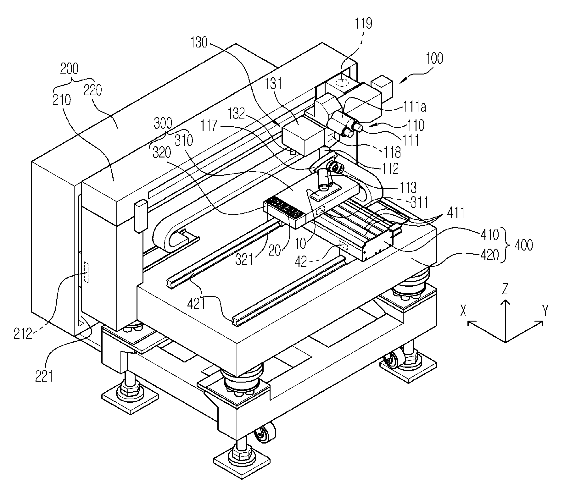
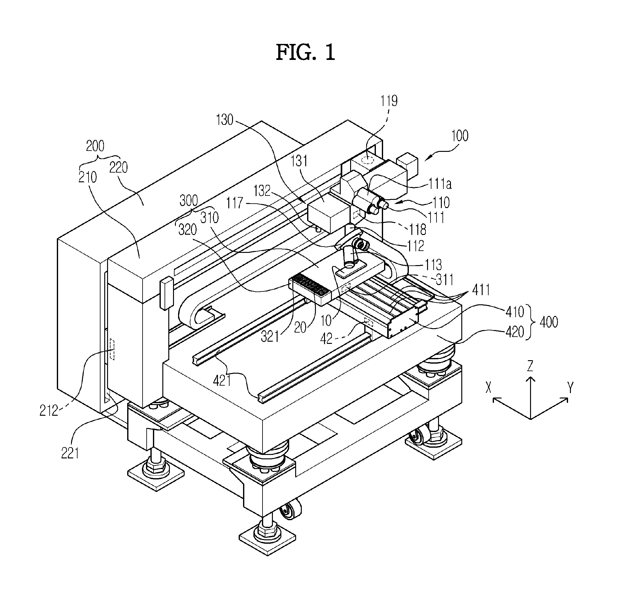
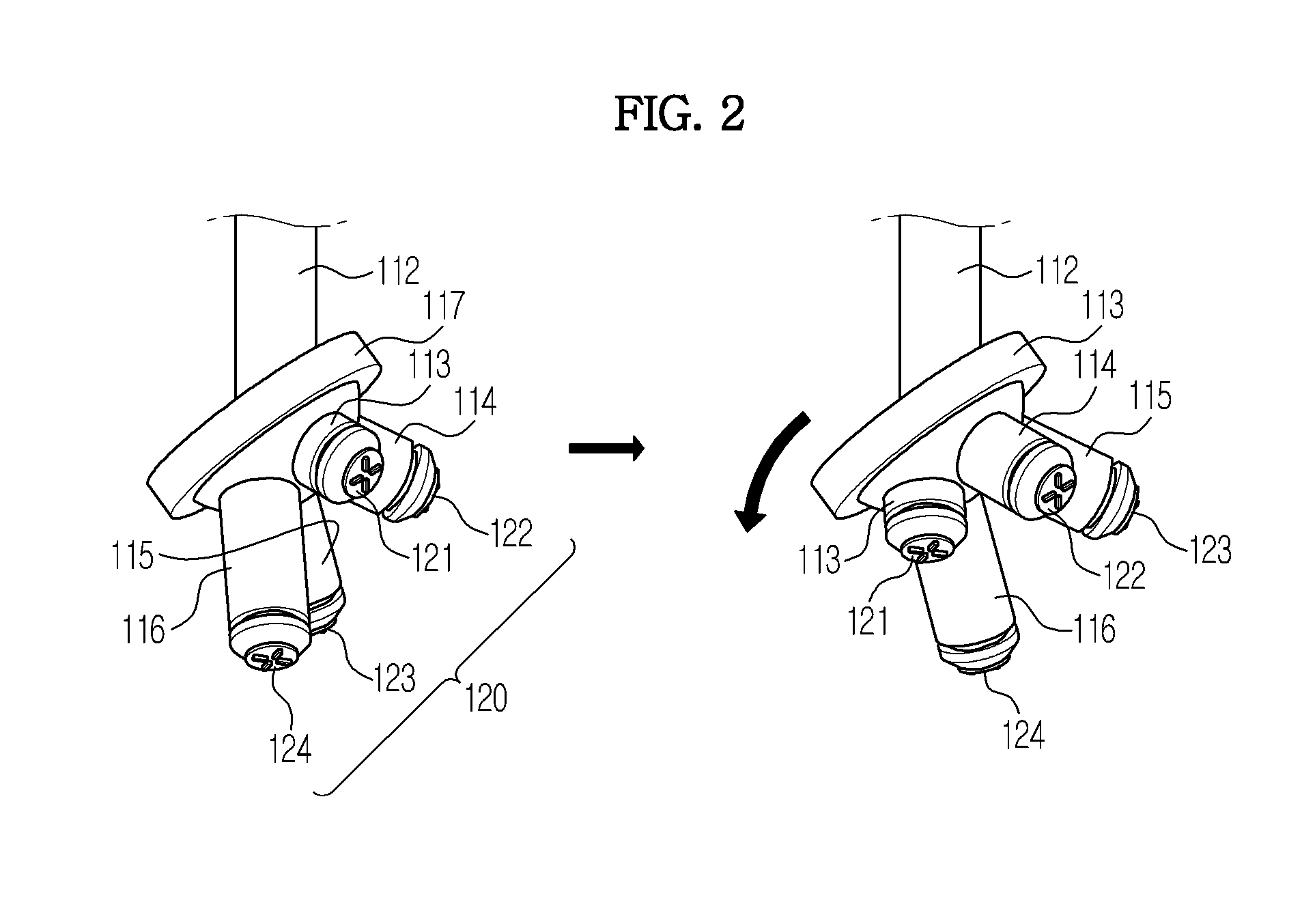
A pattern transfer apparatus including a microscope having an ocular lens provided in a first housing, an objective lens provided in a second housing and a body tube connecting the ocular lens and the objective lens to each other, and a stamp coupled to an opening of the second housing and having a pattern to be transferred to a substrate may be provided. Checking of both defect position and transfer position of the substrate and transferring of the pattern can be performed concurrently through the microscope integrated with the stamp. Accordingly, the repetitive and continuous micro pattern transfer process can be more efficiently and rapidly performed, and the pattern can be more accurately and precisely transferred to the substrate.

Description

CROSS-REFERENCE TO RELATED APPLICATION[0001]This application claims the benefit of Korean Patent Application No. 2011-0134146, filed on Dec. 14, 2011 in the Korean Intellectual Property Office, the disclosure of which is incorporated herein by reference in its entirety.BACKGROUND[0002]1. Field[0003]Example embodiments of the present inventive concepts relate to transfer apparatuses to transfer a pattern to a substrate and / or methods for controlling the same.[0004]2. Description of the Related Art[0005]In general, a photolithography process to form a micro pattern using light is applied to micro sensors, photonic crystal optical devices, micro mechatronic devices, display devices, displays such as field emission displays (FEDs), organic light-emitting diodes (OLEDs) and plasma display panels (PDPs), solar cells and semiconductors.[0006]However, whenever a pattern is formed by using a photolithography process, exposure, development, etching and cleaning processes also should be perfor...

Claims


Application Information

Patent Timeline
Patent Type & Authority Applications(United States)
IPC IPC(8): B29C59/02
CPCG03F7/0002B29C59/026B41F16/00B41F33/00
Inventor LEE, SUNG HOONCHO, YOUNG TAE
Owner SAMSUNG ELECTRONICS CO LTD
Learn More