Method and system for non-linearity compensation in optical transmission systems

Inactive Publication Date: 2013-06-20
OFIDIUM PTY LTD
View PDF25 Cites 14 Cited by
  • Summary
  • Abstract
  • Description
  • Claims
  • Application Information

AI Technical Summary

Benefits of technology

The present invention provides a method for improving the quality of signals transmitted through optical fibers by reducing distortion. This is achieved by using a bandwidth-limiting element such as a low pass filter in the non-linear backpropagation elements of each segment of the link model. This helps to minimize the impact on the accuracy of the backpropagation computation and reduces the need for oversampling. The method also allows for the reduction of the number of segments in the model, reducing computation cost, and the optimization of the parameters of the backpropagation model to further mitigate signal distortion.

Problems solved by technology

Both of the aforementioned coherent optical modulation technologies may be employed to compensate for linear impairments such as CD and PMD, and thus fibre non-linearity is a significant limiting factor of transmission distance in such systems.
While the backpropagation technique has been shown to be highly effective in mitigating the effects of both linear and non-linear distortion, it has the disadvantage of being highly computationally intensive.
However, further reductions in the number of steps will result in significant loss of accuracy.

Method used


Image

  • Method and system for non-linearity compensation in optical transmission systems
  • Method and system for non-linearity compensation in optical transmission systems
  • Method and system for non-linearity compensation in optical transmission systems

Examples


Embodiment Construction

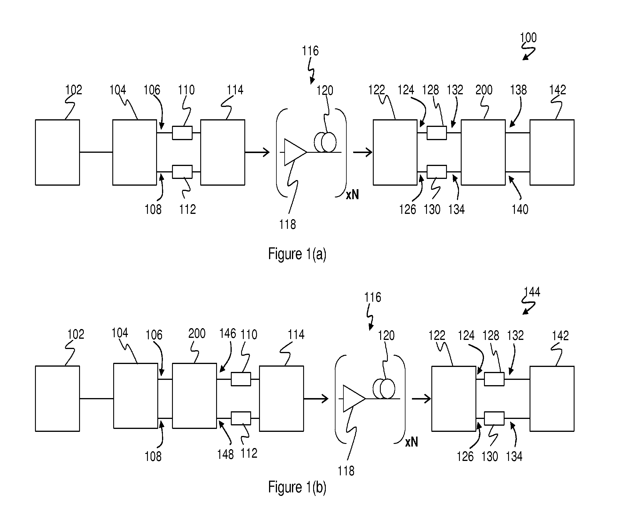
[0050]Embodiments of the present invention provide methods and apparatus for equalisation of signals within optical transmission systems that are subject to a combination of linear and non-linear transmission effects, including chromatic dispersion (CD), polarisation mode dispersion (PMD), and self phase modulation (SPM). More particularly, equalisers are provided to mitigate distortions of the signal resulting from such effects, that are based generally upon the backpropagation technique, with novel modifications providing improved computational efficiency and / or accuracy. Backpropagation equalisers embodying the invention may be deployed at either the transmitting or receiving end of an optical transmission link, and while both of these variants are described generally herein, detailed characterisations and results are presented with particular reference to a post-equalisation embodiment, ie in which the backpropagation equaliser is deployed at the receiving end. It will be unders...


PUM


Abstract

An equaliser (200) for equalisation of a signal transmitted via an optical fibre link from a transmitter to a corresponding receiver employs a backpropagation model (300) which comprises one or more sequential segments collectively representing an inverse fibre link. Each sequential segment comprises a linear backpropagation element (304), and a non-linear backpropagation element (306) having an associated compensation bandwidth (312). The equaliser (200) generates a distortion-mitigated signal by computing, for each sequential segment in turn, a first linear compensated signal from a signal input to the segment in accordance with the linear backpropagation element (304), and a non-linear compensated signal from the first linear compensated signal in accordance with the non-linear backpropagation element (306). Computation of the non-linear compensation signal comprises limiting a bandwidth of a compensation signal derived from the first linear compensated signal in accordance with the associated compensation bandwidth (312).

Description

FIELD OF THE INVENTION[0001]The present invention relates to the field of optical communications, and more particularly to methods and apparatus for performing electrical compensation of linear and non-linear impairments in coherent optical communications systems.BACKGROUND OF THE INVENTION[0002]Optical transmission, in which an information signal is modulated onto an optical carrier, is widely employed in modern communications systems. In particular, wide-area communications networks employ long-haul transmission links using single mode optical fibres for the transmission of digital information at very high bit rates, using one or more optical carriers, or wavelengths, over each fibre. The distance over which data may be transmitted in single mode optical fibres before some form of regeneration is required may be limited by optical attenuation, accumulated noise (eg from optical amplifiers), linear dispersion mechanisms, such as chromatic dispersion (CD) and polarisation mode dispe...

Claims


Application Information

Patent Timeline
IPC IPC(8): H04B10/12H04B10/69
CPCH04B10/6971H04B10/25073H04B10/6161H04B10/6163
Inventor LOWERY, ARTHUR JAMESDU, LIANG BANGYUAN
Owner OFIDIUM PTY LTD
Why Eureka
Try Eureka